TP-6519 8/1736 Section 4 Controller
4.2 Controls and Display
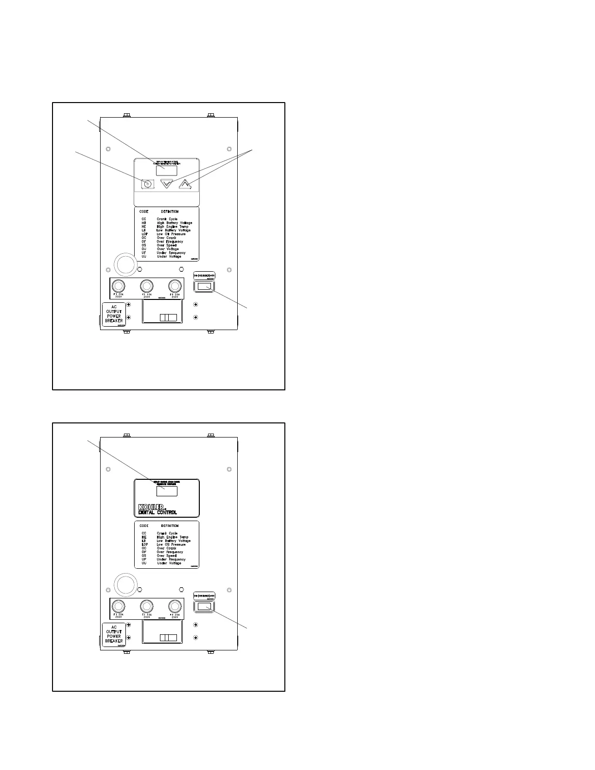
The ADC-RES controller has an LED display and a
three-button keypad. See Figure 4-2. The DC-RET
controller has an LED display. See Figure 4-3.
1
2
4
3
1. LED display
2. Select button (use for setup and adjustment only)
3. Up and down arrow buttons (use for setup and adjustment
only)
4. Generator set master switch (RUN--OFF/RESET-AUTO)
GM28707A-C
Figure 4-2 ADC-RES Controller
1
2
1. LED display
2. Generator set master switch (RUN--OFF/RESET-AUTO)
GM57962
Figure 4-3 DC-RET Controller
A three-position generator set master switch is mounted
on the c ontroller junction box.
4.2.1 Master Switch
The generator set master switch is a three-position
(RUN\OFF/RESET\AUTO) rocker s witch. See
Figure 4-2 or Figure 4-3 for the master switch location.
See Section 5.11 for master switch connections.
4.2.2 LED Display
The LED display shows runtime hours, fault codes,
application program version number, or controller
parameters during configuration and adjustment. See
Figure 4-4.
The LED display is activated by a start or RUN
command as follows:
D Move the master switch to RUN.
D With the mas ter switch in AUTO, send a remote start
command (close the remote start contact across
leads 3 and 4).
The LED display indicates generator set status as
shown in Figure 4-5. When the generator set is running,
engine runtime hours are shown.
When the generator set is running, the arrow keys on
the ADC-RES can be used to step through the other
displays as described in Section 4.2.3.
When the master switch is in AUTO, the display turns off
48 hours after generator set shutdown.
 Loading...


