TP-6519 8/17 71Section 5 Component Testing and Adjustment
13. Start the generator set by moving the generator set
master switch to the RUN position.
14. Check for leaks using a gas leak detector.
15. Move the generator set master switch to the OFF/
RESET position to shut down the generator set.
To convert from LP vapor to natural gas, remove the fuel
orifice and connect the DSAI leads together.
5.12.4 Digital Spark Advance Ignition
(DSAI) Timing
The digital spark advance ignition (DSAI) optimizes the
engine timing for the selected fuel, natural gas or LP.
The location of the DSAI timing leads is shown in
Figure 5-35. Connect the DSAI leads in the air intake
compartment together for natural gas fuel. Disconnect
the leads if LP is used. See Figure 5-35 and
Figure 5-36.
See the engine service manual for ignition system
service information.
DSAI Timing Lead Connection
Natural Gas Connect
LP Disconnect
Figure 5-36 DSAI Lead Connection
5.13 Circuit Protection
If the generator set circuit breaker trips or the fuses blow
repeatedly, see Section 3, Troubleshooting, for possible
causes.
5.13.1 Line Circuit Breaker
A line circuit breaker interrupts the generator output in
the event of a fault in the wiring between the generator
and the load. The line circuit breaker location is shown
in Figure 1-1. The circuit breaker rating is 70 amps. If
the c ircuit breaker trips, reduce the load and switch the
breaker back to the ON position. With the breaker in the
OFF position the generator set runs but the generator
output is disconnected from the load.
5.13.2 Fuses
Three panel-mounted fuses protect the alternator and
electrical controls. See Figure 1-1 for fuse locations. A
battery charger fuse is located in the positive battery
lead. Always check for and replace any blown fuses
before replacing other components.
See Figure 5-37 for fuse part numbers. Always identify
and correct the cause of a blown fuse before restarting
the generator set. Refer to Section 3, Troubleshooting,
for conditions that may indicate a blown fuse. Replace
blown fuses with identical replacement parts.
Fuse Rating, Amp Label Part Number
Auxiliary winding 20 F1 292937
Relay interface
board
10 F2 223316
Controller 10 F3 223316
Battery charger 10 — AGS 10
Figure 5-37 Fuses
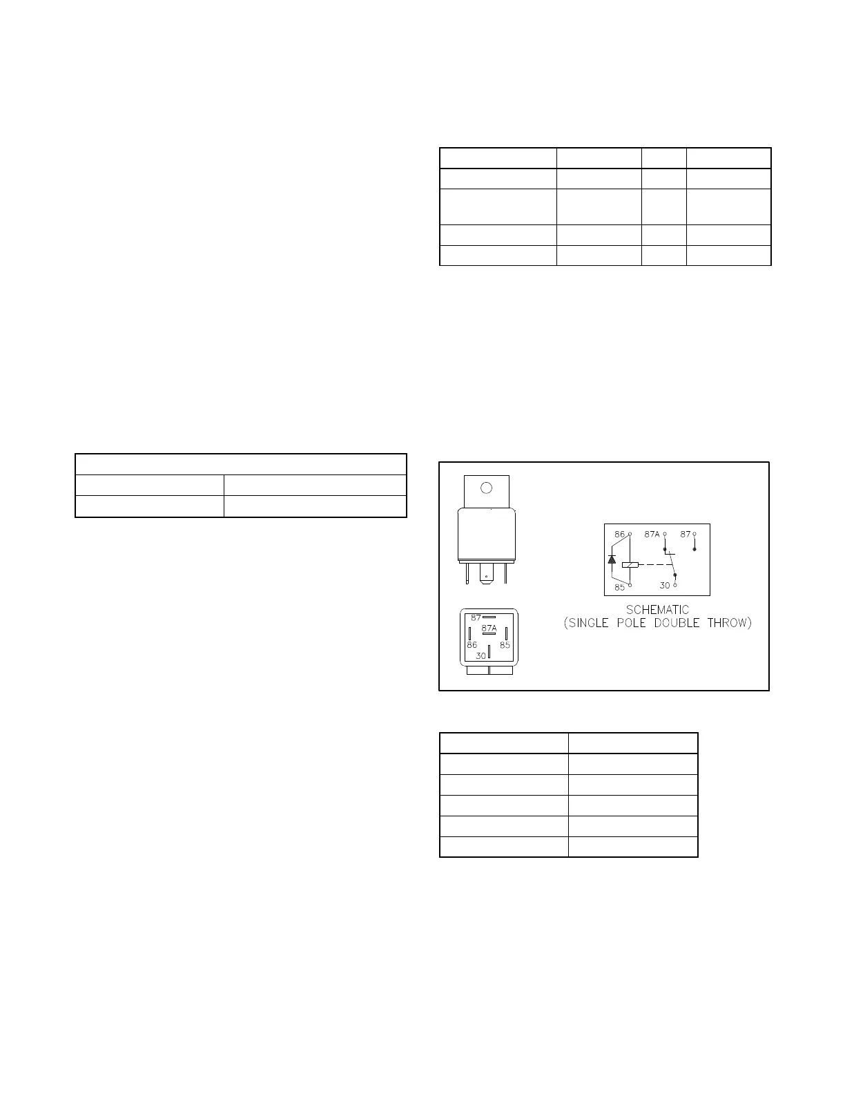
5.14 Starter Relay
The starter relay contains an internal diode across the
relay coil. See Figure 5-38. Continuity checks across
the coil terminals will show continuity (low resistance) in
one direction and an open circuit in the other.
Figure 5-39 shows the starter relay connections.
259391
Figure 5-38 Starter Relay
Relay Terminal Lead
30 14P
85 N7
86 71
87 14S
87A NC
Figure 5-39 Starter Relay Connections
 Loading...


