TP-6519 8/17 35Section 4 Controller
Section 4 Controller
4.1 Introduction
This section covers operation, configuration,
adjustment, and replacement of the ADC-RES and
DC-RET controllers. See Section 3 for troubleshooting
procedures.
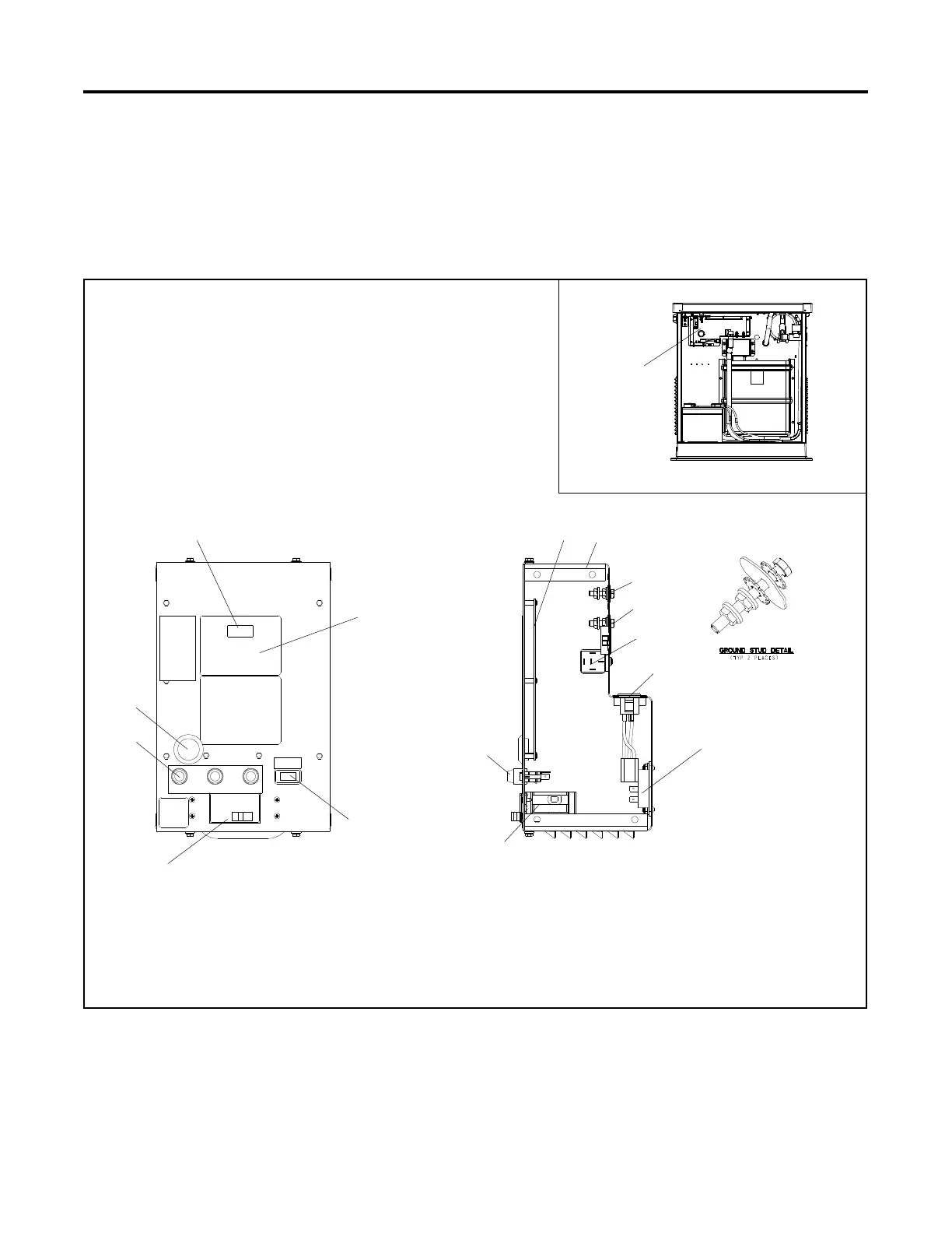
See Figure 4-1 for the controller location.
1. Controller display
2. Keypad (ADC-RES only; see Figure 4-2)
3. Generator set master switch (RUN-OFF/RESET-AUTO)
4. Line circuit breaker (load connection)
5. Fuses F1, F1, and F3
6. Serial port for communication connection (remove plug to access)
7. Logic board
GM57962
10
12
11
4
4
3
6
9
13
5
1
2
5
78
Location
Top View
8. Optional relay board location
9. L0 stud
10. Ground stud
11. Start relay
12. Receptacles for battery charger and optional
carburetor heater power connection
13. SCR module
Figure 4-1 Controller Components
 Loading...


