TP-6071 3/00 19Section 6 Controller Troubleshooting
Section 6 Controller Troubleshooting
6.1 Controller
This section covers the controller troubleshooting
procedure for generator sets equipped with a relay
controller and related engine components. Refer to the
operation manual to identify the controller’s external
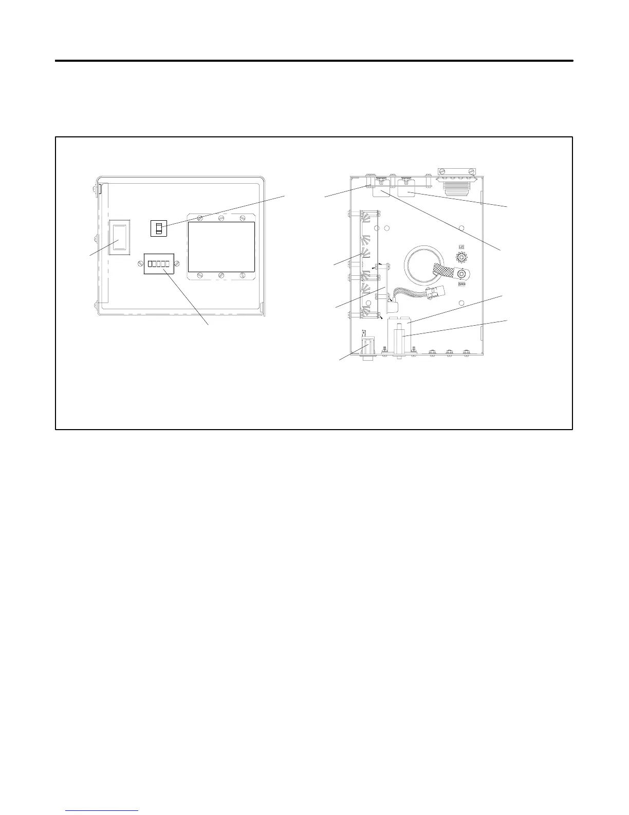
components. Refer to Figure 6-1 to identify the
controller’s internal components.
A-359146
7
5
2
3
6
4
1
AC--CIRCUIT
BREAKER
START
STOP/
HOUR
METER
BREAKER
DC--CIRCUIT
PREHEAT
1. Controller circuit board
2. K25 relay
3. K20 relay
4. Hourmeter
5. DC circuit breaker
6. Start/stop switch
7. Voltage regulator circuit board
8. Overspeed circuit board (opt.)
8
6
5
4
Figure 6-1 Controller Internal Components
 Loading...


