TP-6071 3/0046 Section 9 Generator Disassembly/Reassembly
5588610
1
2
3
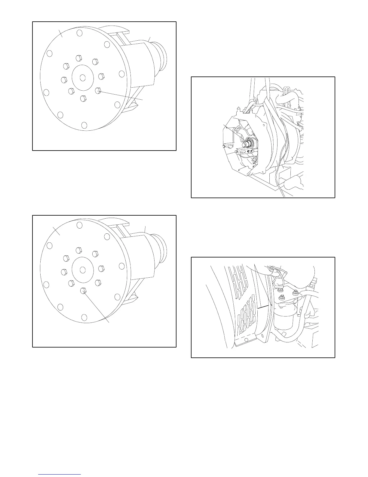
1. Drive disc
2. Rotor
3. Bolt
Figure 9-9 Drive Disc
9.2 Reassembly
1. Clamp the rotor in a soft-jaw vise. Install a new
drive disc on the rotor. Tighten the eight bolts to
38 Nm (28 ft. lbs.) See Figure 9-10.
5588611
1
2
3
1. Drive disc
2. Rotor
3. Bolt
Figure 9-10 Drive Disc Installation
2. Install the rotor/drive disc assembly on the engine
flywheel using eight washers and bolts. Tighten
the bolts to 19 Nm (14 ft. lbs.)
3. Align the fan to the rotor/drive disc assembly using
the mark created in the disassembly procedure.
Install the fan to the drive disc using eight screws,
four spacers, washers, and locknuts.
Note: Install the fan with the flange side facing
away from the flywheel.
4. Replace the O-ring in the end bracket bearing bore.
Use a sling to support the stator assembly while
installing the stator over the rotor. Do not damage
the rotor. See Figure 9-11.
5588612
1
1. O-ring
Figure 9-11 Stator Installation
5. Install the four overbolts (the two long bolts in the
lower holes). Check that the alignment marks on
the stator housing and locator plate match. See
Figure 9-12. Tighten the overbolts to 33.9 Nm
(25 ft. lbs.)
5588613
1
1. Alignment marks
Figure 9-12 Alignment Marks
6. Use the hoist to raise the alternator end. Remove
the wood block from under the locator plate. Lower
the generator set and install a bolt, a large washer,
two small washers, and a locknut on each
vibromount. Tighten the mounting bolts to 28 Nm
(20 ft. lbs.).
 Loading...


