TP-6071 3/0032 Section 7 Generator Troubleshooting
7.6 Voltage Regulator Adjustment
The voltage regulator is factory-set and under normal
circumstances requires no further adjustment.
However, if the voltage regulator has been replaced or
tampered with, or if voltage/frequency reconnection has
been done, readjust the voltage regulator according to
the following procedure. The voltage regulator
components are identified and described in the
following paragraphs. See Figure 7-5 for voltage
regulator connection.
Voltage Adjustment Potentiometer. Potentiometer
adjusts the generator output.
Stability Potentiometer. Potentiometer fine-tunes the
regulator circuitry to reduce light flicker.
Volts/Hz Potentiometer. Potentiometer adjustment
determines the engine speed (Hz) at which the
generator output begins to drop.
66 55 4
3
AC
F+
8
7
6
5
4
3
2
1
Input
Green
Output
Red
V/HZ
Stab
Sensing
Yellow
B1 B2
2
1
F--
AC
AC
Vol ts
1
2
4
5
6
7
3
TP-5983-7
1. Sensing leads
2. Main field (rotor)
3. Stator windings
4. Rectifier
5. Armature
6. Exciter field
7. Voltage regulator power supply leads
Figure 7-5 PowerBoostt V Voltage Regulator
Connection
TP-5983-7
8
7
6
5
4
3
2
1
Input
Green
Output
Red
STAB
Sensing
Yellow
V/HZ VOLTS
1
2
3
4
5
6
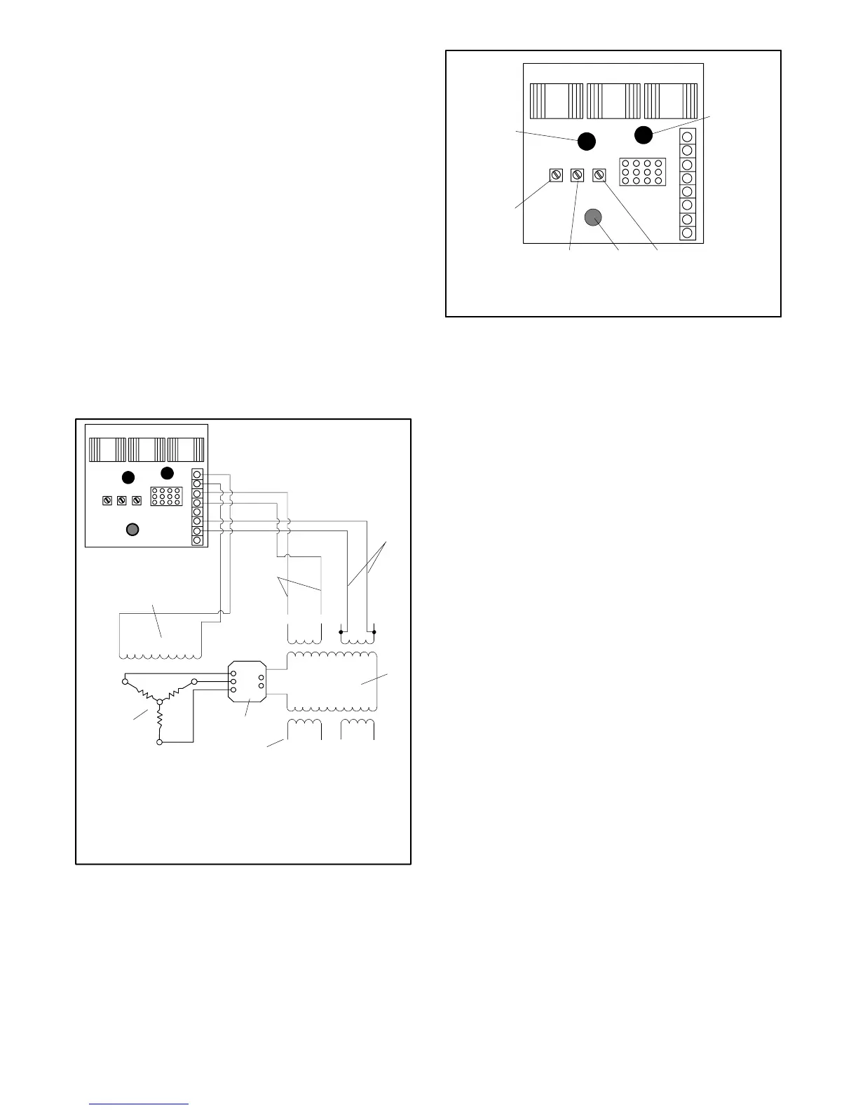
1. LED1 (green input power)
2. LED2 (red output on)
3. Voltage potentiometer
4. LED3 (yellow sensing)
5. Volts/Hz potentiometer
6. Stability potentiometer
Figure 7-6 PowerBoosttV Voltage Regulator
Voltage Regulator Adjustment Procedure:
1. Place the generator set controller start/stop switch
in the STOP position.
2. Turn the Volts/Hz and the stability potentiometers
fully counterclockwise. Connect the voltmeter to
the AC c ircuit or an electrical outlet. Refer to
Figure 7-6.
3. Start the generator set and rotate the voltage
adjustment potentiometer clockwise (increase
voltage) or counterclockwise (decrease voltage)
until the desired output voltage is achieved.
4. Connect a 120-volt test light to the generator
receptical. Rotate the stability potentiometer
clockwise until the test light flickers minimally.
5. Readjust the voltage adjustment potentiometer
until the desired output voltage is achieved.
6. Adjust the engine speed to the specified cut-in
frequency as measured on the frequency meter.
The factory setting is 57.5--58 Hz for 60 Hz models
and 47.5--48 Hz for 50 Hz models.
 Loading...


