TP-6071 3/00 23Section 6 Controller Troubleshooting
6.3.3 Overspeed Safety Shutdown (SDR)
When the engine speed exceeds 70 Hz (2100 rpm), the
shutdown relay (SDR) on the overspeed protection
circuit board energizes. The normally open SDR
contacts close to complete the circuit and energize the
K4 relay (LED4 lights).
The normally closed K4 contacts open to deenergize the
K25 relay. The closed (normally open) K25 contacts
open to deenergize the fuel solenoid.
The normally open K4 contacts close to maintain a
ground to the K4 relay.
As the generator set shuts down, the K1 relay
deenergizes (LED1 goes out). The normally open K1
contacts open to deenergize the K2 relay (LED2 goes
out). The normally closed K2 contacts close to ground
the circuit to the K4 relay until the generator set comes to
a complete stop.
6.4 Controller Circuit Board
Some controller circuit board components can be tested
without removing the component from the circuit board.
Test the components before replacing the circuit board.
Refer to Section 6.5, Troubleshooting Flow Chart.
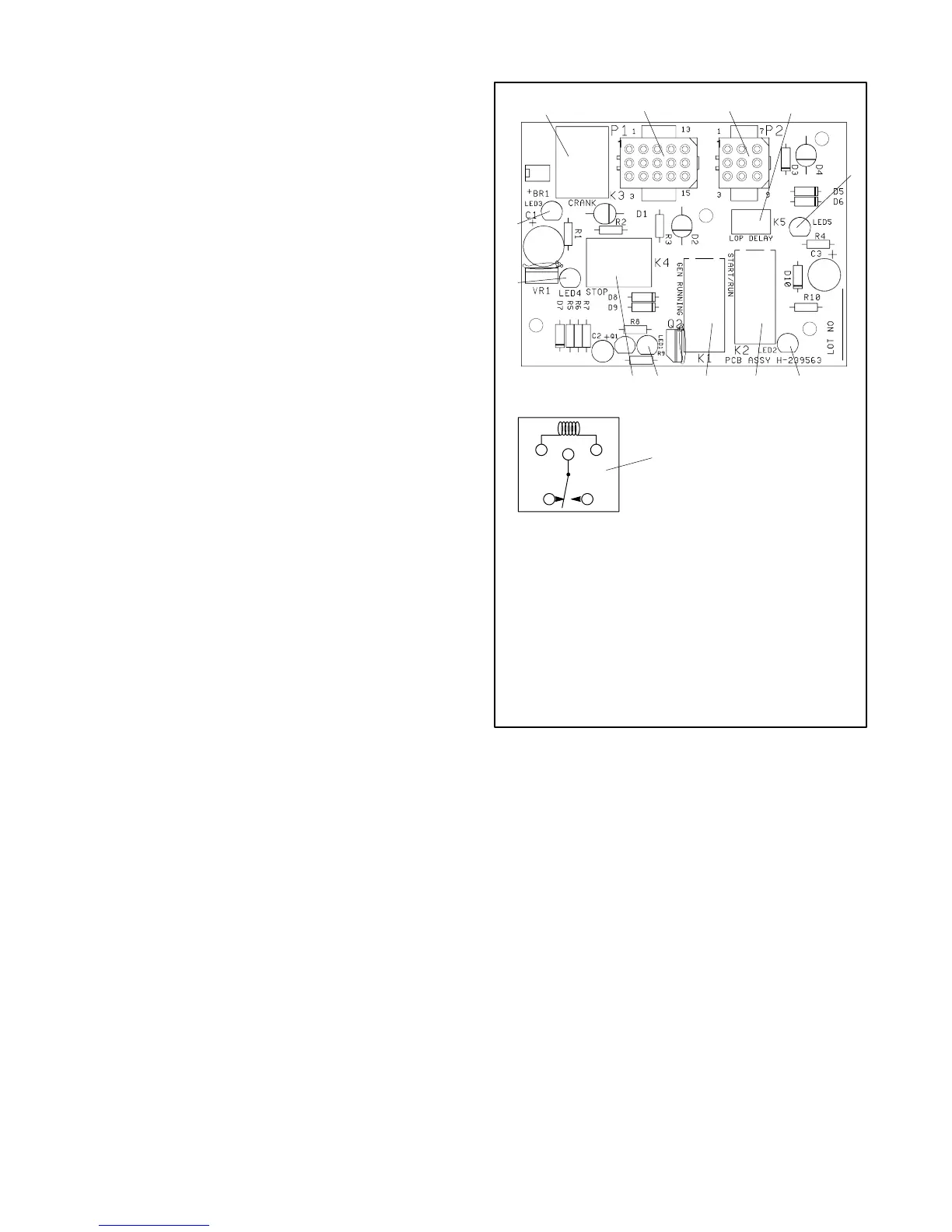
The controller circuit board has light-emitting diodes
(LEDs) that indicate relay coil power and aid in circuit
board and generator fault detection. When any of relays
K1--K5 receives power the corresponding LED lights.
The LED does not indicate whether the relay coil is
energized. Determine if the relay coil is energized by
analyzing the generator faults by performing a continuity
test on the relay coil. See Figure 6-4.
H--239563
2
4
5
6
7
8
910
11
12
1
3
13
1. Engine crank control relay (K3)
2. P1 connector
3. P2 connector
4. Time delay relay (K5)
5. LED5
6. LED2
7. Engine run relay (K2)
8. AC crank disconnect relay (K1)
9. LED1
10. Fault shutdown relay (K4)
11. LED4
12. LED3
13. Relay schematic
Figure 6-4 Controller Circuit Board
 Loading...


