TP-6071 3/00 39Section 8 Component Troubleshooting
Section 8 Component Troubleshooting
8.1 General
See Figure 8-1 through Figure 8-3 for component
testing.
With the generator set battery connected, check the
generator wiring harness and the components listed in
the following tables. Check each component using a
multimeter to verify that the switches function and that
voltage is present at each component.
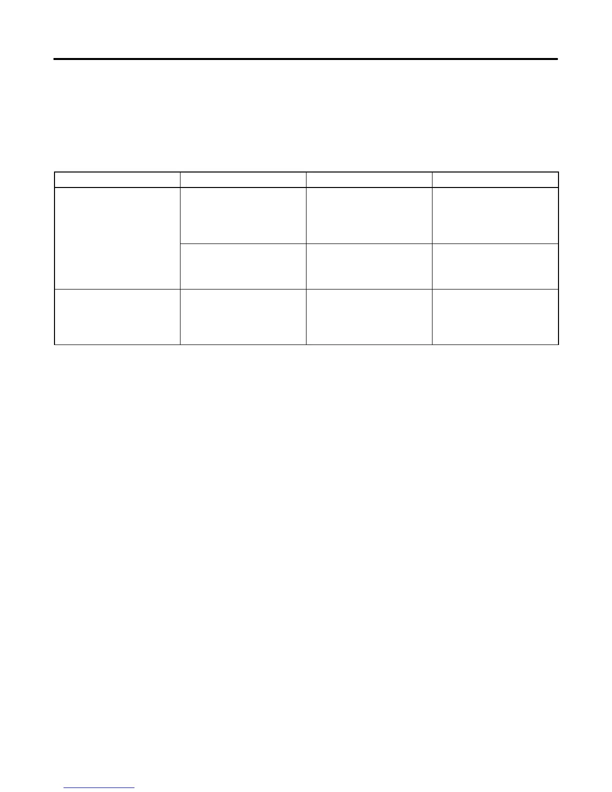
Component Voltmeter Connections Procedure Results
Hourmeter and wiring Connect the red test lead to the
hourmeter positive (+) terminal.
Connect the black test lead to
the hourmeter negative (--)
terminal.
Set the voltmeter to 12 volts DC
or greater. Start the generator
set.
A 12 volt DC reading indicates
the wiring harness is functional.
None (see Procedure) Disconnect the hourmeter leads
and apply 12 volts DC to the
hourmeter. The hourmeter is
polarity sensitive.
If functional—hourmeter
operates.
Stator auxiliary winding
B1 and B2
Connect the AC voltmeter leads
to the B1 and B2 windings at
connector P11.
Stop the generator set. Connect
a voltmeter to the B1 and B2
windings. Crank the generator
set and allow the set to reach its
rated speed.
A reading of 12--15 volts AC
indicates a functional B1/B2
winding.
Figure 8-1 Engine/Generator Component Testing—Relay Controller (Sheet 1 of 3)
 Loading...


