TP-6071 3/0034 Section 7 Generator Troubleshooting
7.8 Exciter Armature
The exciter armature supplies excitation current to the
generator main field through the rectifier module. Test
the exciter armature as described in the following steps.
Exciter Armature Test Procedure:
1. Disassemble the alternator. Refer to Section 9.
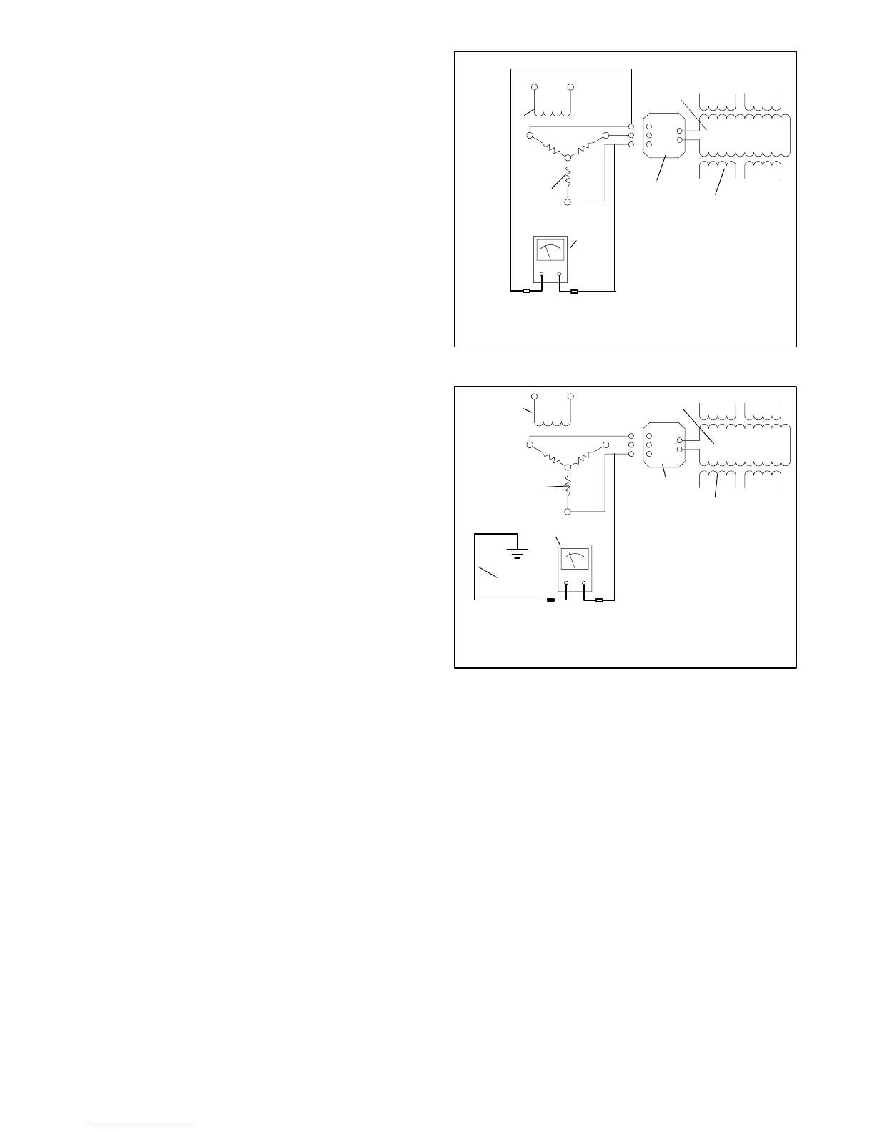
2. With the alternator disassembled, disconnect the
armature leads from the rectifier module AC
terminals. Refer to Section 9.
3. With an ohmmeter on the R x 1 scale, check the
resistance across the exciter armature leads. See
Figure 7-9. See Section 1, Specifications for the
armature resistance. No continuity indicates an
open armature winding. If the resistance test is
inconclusive, perform a megohmmeter test on the
exciter armature as described in the next step.
Note: Most ohmmeters will not accurately
measure less than one ohm. Consider the
exciter armature functional if the resistance
reading (continuity) is low and there is no
evidence of a shorted winding (heat
discoloration).
4. Check the exciter armature winding for a
short-to-ground condition. Use a megohmmeter to
apply 500 volts DC to either armature lead and the
armature frame. Follow the megohmmeter
manufacturer’s instructions for using the
megohmmeter. See Figure 7-10. A reading of
approximately 1.5 MOhms and higher indicates the
exciter armature is functional. A reading of less
than approximately 1.5 MOhms indicates
deterioration of the winding insulation and possible
current flow to ground; If so, replace the exciter
armature.
F+
F--
AC
AC
AC
1
2
3
4
5
6
TP-5983-7
1. Main field (rotor)
2. Stator windings
3. Rectifier module
4. Ohmmeter
5. Armature
6. Exciter field
Figure 7-9 Exciter Armature Ohmmeter Test
F+
F--
AC
AC
AC
1
2
3
4
5
6
7
TP-5983-7
1. Main field rotor
2. Stator windings
3. Rectifier module
4. Megohmmeter
5. Shaft connection
6. Armature
7. Exciter field
Figure 7-10 Megohmmeter Connections on
Exciter Armature
 Loading...


