TP-6071 3/0036 Section 7 Generator Troubleshooting
F+
F--
AC
AC
AC
TP-5983-7
1
2
5
4
6
7
8
3
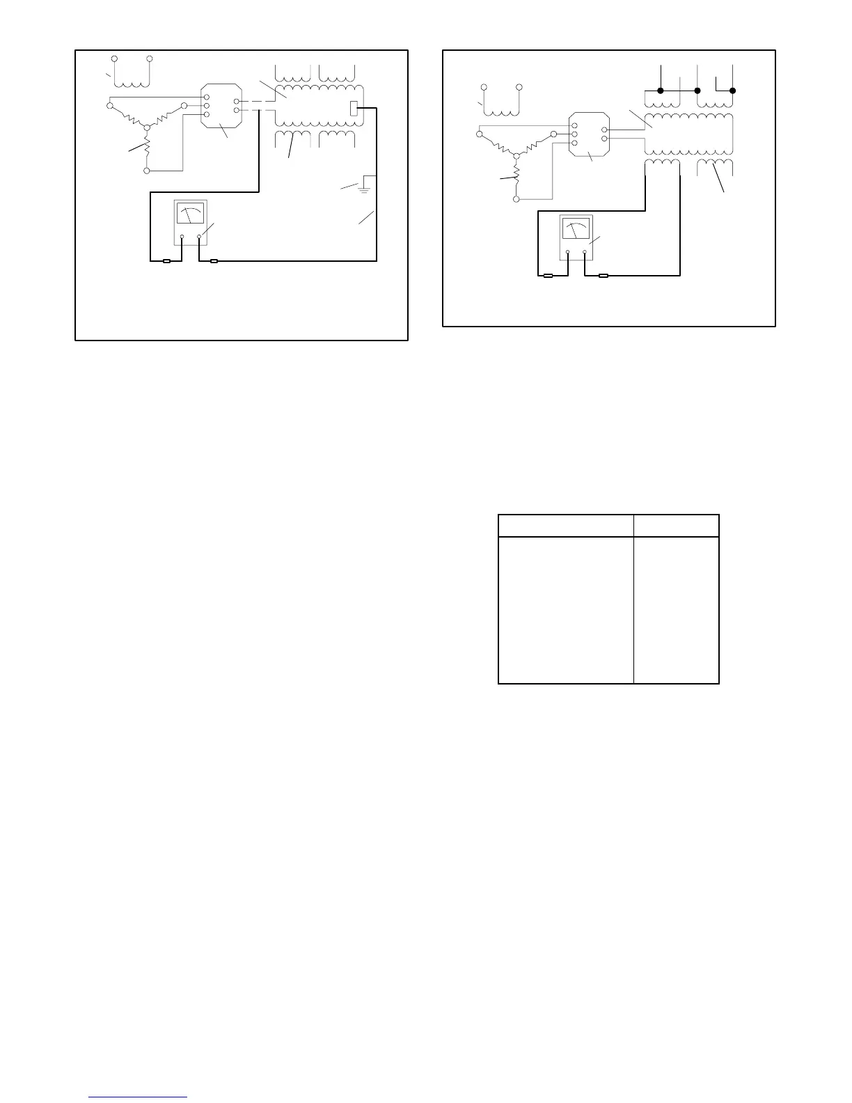
1. Main field (rotor)
2. Stator windings
3. Frame connection
4. Shaft connection
5. Rectifier module
6. Megohmmeter
7. Armature
8. Exciter field
Figure 7-13 Megohmmeter Connections on
Main Field
7.11 Stator
The stator consists of a series of coils of wire laid in a
laminated steel frame. The stator leads supply voltage
to the AC load and exciter regulator.
Before testing the stator, inspect it for heat discoloration
and visible damage to the housing lead wires and
exposed and varnished areas of the frame laminations.
Be sure the stator is securely fastened in the stator
housing.
The stator produces electrical output (AC) as the
magnetized main field rotates within the stator windings.
Test the condition of the stator according to the following
procedure.
Leads 1, 2, 3, and 4 are the generator output leads.
Leads 55 and 66 are the voltage regulator supply and
sensing leads. The output of leads B1 and B2 is rectified
by BR1 to supply the control voltage. BR1 is located on
the controller circuit board. Refer to the schematic in
Figure 7-14 when performing the following tests.
Stator Test Procedure:
1. Place the start/stop switch in the STOP position.
2. Disconnect the generator set engine starting
battery, negative (--) lead first.
3. Check the generator output lead connections. See
Section 10, Wiring Diagrams.
F+
F--
AC
AC
AC
TP-5588-7
F1 F2
33 3
55 44
4
12B1 B2
1
2
3
4
5
6
1. Main field (rotor)
2. Stator windings
3. Rectifier module
4. Ohmmeter
5. Armature
6. Exciter field
Figure 7-14 Stator Ohmmeter Connections
4. Disconnect all the stator leads to isolate the
windings. To check the stator continuity, set the
ohmmeter on the R x 1 scale. Check the stator
continuity by connecting the meter leads to the
stator leads as shown in Figure 7-14. See
Figure 7-15 for single-phase and Figure 7-16 for
three-phase values. Perform the stator tests on all
the stator windings.
Between leads Continuity
1 and 2
3 and 4
55 and 66
B1 and B2
1 and 3, 4, 33, 44
1 and 55, B1, and B2
4 and B1 and B2
55 and B1 and B2
Any stator lead and
ground
Yes
Yes
Yes
Yes
No
No
No
No
No
Figure 7-15 Stator Continuity 1-Phase
 Loading...


