TP-6071 3/0030 Section 7 Generator Troubleshooting
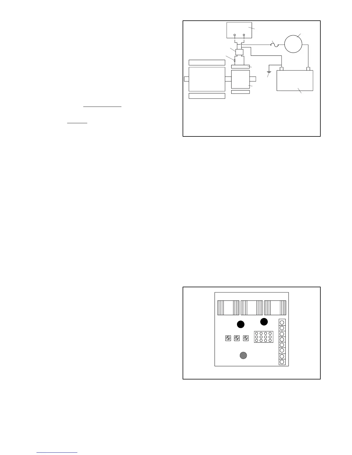
3. Connect a separate excitation circuit as shown in
Figure 7-2. Connect an ammeter and a 10-amp
fuse in series with F1. Note and record the
ammeter reading.
4. The approximate ammeter reading should equal
battery voltage divided by the sum of the specified
exciter resistances (cold). Disconnect the resistor
leads and determine the exciter current value using
an ohmmeter. See Section 1, Specifications for the
normal values.
Exciter Current =
B
ttery
olt
ge
Exciter Resistance
Example :
12 VDC
3.5 Ohms
= 0.6 Amps
5. Start the engine and check that the ammeter
remains stable. An increasing meter reading
indicates a shorted exciter field. A decreasing
meter reading to zero or an unstable reading
suggests a running open in the exciter. If the
ammeter is stable, continue with step 6.
6. Check for AC output across the stator leads and
compare the output to the values in Section 1,
Specifications. If the output varies considerably
from those listed, a faulty stator, rotor, rectifier
module, or armature is the likely cause.
If the AC output is not within specifications, the voltage
regulator is probably inoperative. If there is no
generator output during normal operation, but output is
available when the generator set is separately excited,
the voltage regulator is probably inoperative.
Note: See Section 1, Specifications for the stator output
voltages (with separately excited generator).
These specifications are based on a battery
voltage of 12 volts. Should the battery voltage
vary (11--14 volts), the resulting stator output
values will also vary.
+—
+—
F1 F2
P6
1
2
3
4
5
6
7
8
9
TP-5983-7
1. Voltage regulator
2. 10-amp fuse
3. DC ammeter
4. Battery
5. Ground
6. Exciter armature
7. Exciter field
8. 10- or 15-ohm resistor
9. P6 connector
Figure 7-2 Separate Excitation Connections
7.4 PowerBoostt V Voltage
Regulators
The generator set is equipped with a PowerBoostt V
voltage regulator. See Figure 7-3. The PowerBoostt V
voltage regulator monitors output voltage to control the
current to the generator exciter field. The voltage
regulator has an underfrequency unloading feature that
is referred to as volts-per-Hz (V/Hz). To determine if the
voltage regulator is functioning, reduce the engine
speed (Hz) and watch for a corresponding drop in the
AC voltage. The AC voltage should remain constant
until the engine speed drops below 57.5 Hz on 60 Hz
models, or 47.5 Hz on 50 Hz models. When the
frequency drops below either 57.5 or 47.5 Hz, the AC
voltage should decline. Perform the following test to
check the regulator output.
TP-5983-7
PowerBoostt
tt
t V
8
7
6
5
4
3
2
1
Input
Green
Output
Red
STAB
Sensing
Yellow
V/HZ VOLTS
Figure 7-3 PowerBoostt V Voltage Regulator
 Loading...


