184 Section 9 Gas Fuel Systems TP-6356 4/12
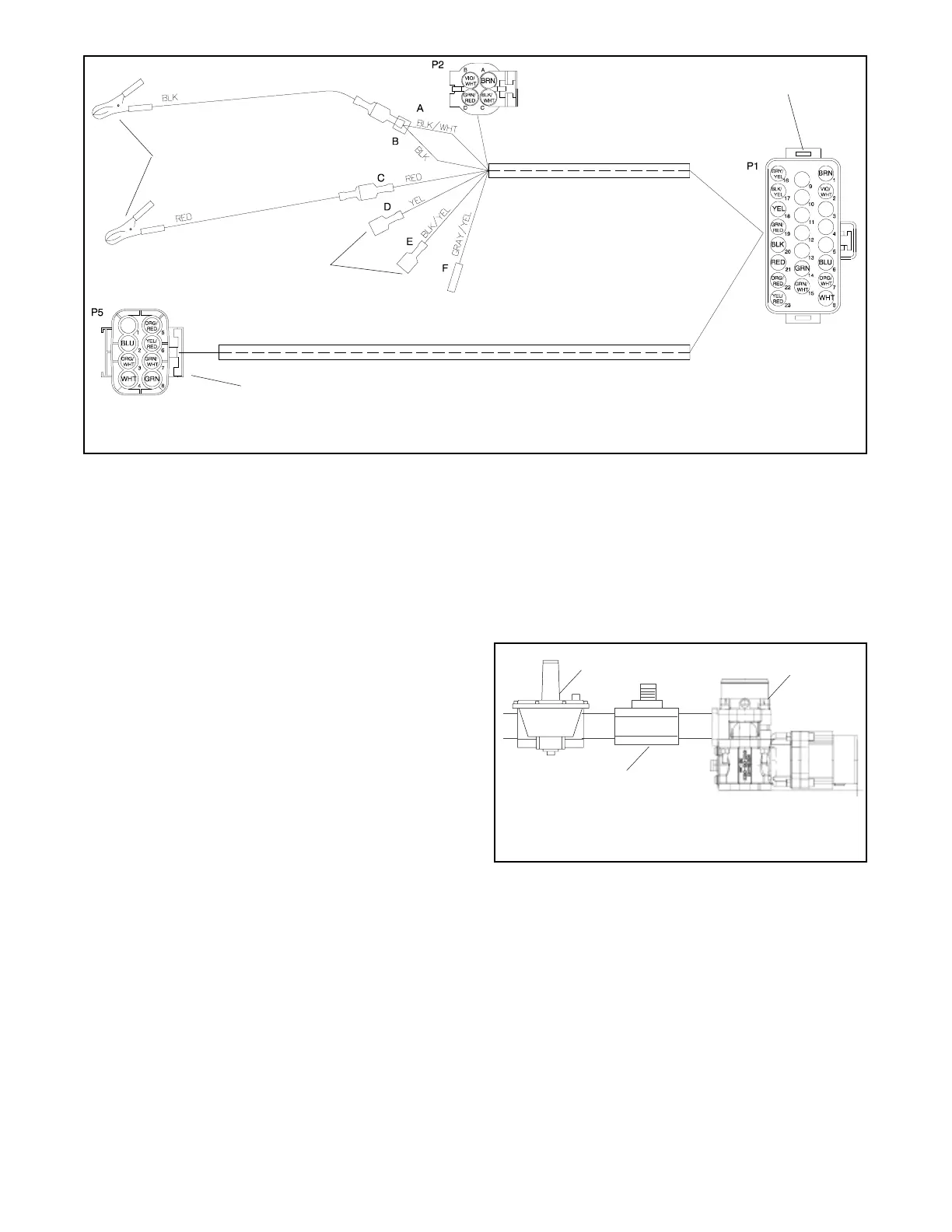
1. Battery power supply connection
2. Digital voltmeter (DVM) connection
3. Air/fuel control module connection
4. Oxygen sensor connection
GM28981-A
1
2
3
4
Figure 9-47 Sensor Interface Harness GM28981 Electrical Connections
c. Place the controller master switch in the RUN
position to start generator set.
d. Allow the generator set to run until the
generator set reaches normal operating
temperature. The time required to reach
normal operating temperature depends
primarily on the ambient temperature and the
size of the engine.
e. With the generator set at normal operating
temperature, apply 90%--100% of rated load. If
a load bank is not available, apply a load at
least comparable to what is generally
connected to the generator set.
f. Verify that the fuel pressure is within
7--11 inches of water at full load. Adjust the
primary fuel regulator as necessary to achieve
the fuel pressure of 7--11 inches of water as
measured at the inlet side of the generator set
fuel solenoid valve.
g. Remove the load and allow the generator set to
run unloaded to cool for at least 5--10 minutes.
h. Place the controller master switch in the OFF
position to stop generator set.
8. Adjust the fuel mixture.
Choose the procedure based on the type of gas
mixer on the generator set.
a. 30--60 kW generator sets. Venturi style gas
mixer used with an integrated throttle body
governor on 4.3 L, 5.0 L, and 5.7 L GM engines.
Also similar to the IMPCO model 100 used on
the 30 kW with 3.0 L GM engine. See
Figure 9-48.
1. Zero pressure fuel regulator
2. Fuel mixture adjustment
3. Venturi style gas mixer
3267
1
2
3
Figure 9-48 30--60 kW with Venturi Style Fuel Mixer
D Placethecontrollermasterswitchinthe
RUN position to start generator set.
D Allow generator set to run until the generator
set reaches normal operating temperature.
D Apply 90%--100% of full rated load.
 Loading...
