186 Section 9 Gas Fuel Systems TP-6356 4/12
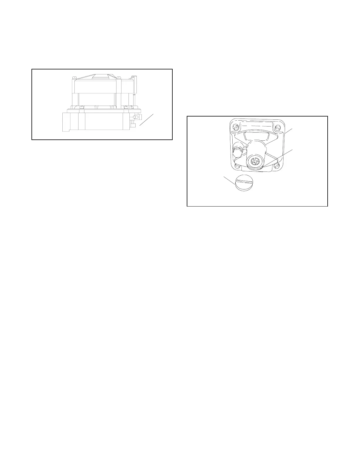
c. 100/125 kW (with single fuel) generator
sets. Nolff N16-475-5A and N16-475-9A style
gas mixers used on 100 kW 8.1 L GM and 125
kW 8.1 L GM turbocharged engines. See
Figure 9-51. This gas mixer style does not
have a fuel mixture adjustment.
1. Idle mixture adjustment
GM28966
1
Figure 9-51 100/125 kW with Nolff 475 Style Fuel
Mixer
D Adjust the fuel regulator adjustment screw to
the approximate midpoint of its adjustment
range. See Figure 9-49.
D Placethecontrollermasterswitchinthe
RUN position to start the generator set.
D Allow the generator set to run until the
generator set reaches normal operating
temperature.
D Apply 90%--100% of full rated load.
D Adjust the fuel regulator adjustment screw to
obtain a full load oxygen sensor voltage
reading in the range specified in Figure 9-44.
D Disconnect the load.
D Adjust the idle mixture adjustment
(Figure 9-51) to obtain a no load oxygen
sensor voltage reading within specifications.
If the oxygen sensor specification cannot be
met at no load, turn the idle mixture screw
out to the richest possible setting (2--2.5
turns).
D Repeat the steps from applying full rated
load to adjusting the idle mixture to obtain a
no load oxygen sensor voltage reading
within specifications to verify the settings.
D Place the controller master switch in the OFF
position to stop generator set.
9. 125 kW (with dual fuel) generator set. Dual fuel
units have a closed loop fuel control system that will
automatically make adjustments in order to
maintain a fuel/air mixture reading of approximately
2.4 volts using UEGO oxygen sensor.
a. Connect a PC laptop with monitoring software.
Reference TP-6215 for instructions on how to
use the software.
b. Adjust the fuel regulator adjustment screw to
the approximate midpoint of its adjustment
range. See Figure 9-52.
SB-527
1. Fuel regulator
2. Adjustment screw
3. Cover plug
1
2
3
Figure 9-52 Fuel Regulator, Typical
c. Place the generator set master switch in the
RUN position to start the generator set.
d. Allow the generator set to run until the
generator set reaches normal operating
temperature.
e. Apply 90%--100% of full rated load.
f. Use the PC laptop and go to the Faults page
and locate the Primary Trim Valve (FTV)
parameter shown in the middle of the page to
the right. Adjust the fuel regulator adjustment
screw until the FTV indicates between 30% and
60%.
g. Disconnect the load.
h. Adjust the idle mixture adjustment
(Figure 9-51) to obtain a no-load oxygen
sensor voltage reading within specifications. See
Figure 9-44.
If the oxygen sensor specification cannot be
met at no-load, turn the idle mixture screw out
to the richest possible setting (2--2.5 turns).
i. Repeat steps e. through h. to verify the settings.
j. Place the generator set master switch in the
OFF position to stop generator set.
 Loading...
