Operator Cab And Controls - Section 32 8/11 OM3245
Page 32-28
NOTE: The ORBCOMM modem installed from the
factory on all new trucks may not be approved for
use in certain countries of the world. Local regulation
may prohibit the use of the ORBCOMM modem/
satellite communicator. Depending on local
regulation, you may need to either remove the
modem or disconnect it and remove the antenna.
Check with KAC service for assistance and preferred
action in your area.
The following is a list of "at risk" countries: China,
Russia, Serbia, Tanzania, Senegal, Zambia,
Botswana and Namibia.
When data store button (1, Figure 32-11) is pressed
on the back side of the center console, it will store a
“snapshot” of the electric drive system. It will also
trigger the KOMTRAX Plus system to store a
“snapshot” of the truck operating system. Indicator
light (2, Figure 32-11) will stay illuminated while the
KOMTRAX Plus system is recording the “snapshot”,
which lasts for 7.5 minutes.
The KOMTRAX Plus system is turned on by the truck
key switch. Immediately after receiving 24V power
from the key switch, the KOMTRAX Plus controller
begins the power-up initialization sequence. This
sequence takes about three seconds, during which
time red LED digits (7, Figure 32-12) display a
circular sequence of flashing LED segments.
During normal truck operation, the red LED digits on
the KOMTRAX Plus controller will count from 00-99
continuously.
When the key switch is turned OFF, the KOMTRAX
Plus controller will remain on while it finishes
processing internal data and saves the recent data
into permanent memory. When the data has been
safely stored, the two digit LED display will turn OFF.
This process could take up to three minutes to
complete.
If 24V power is disconnected (using the battery
disconnect switches) from the KOMTRAX Plus
controller before it has completed its shut down
procedure, the KOMTRAX Plus controller will
lose all data gathered since the key switch was
last turned ON. Do not disconnect battery power
until the KOMTRAX Plus controller has
completed the shut down procedure and has
turned the LED digits off.
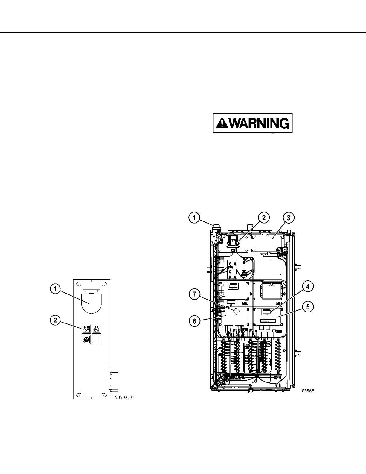
FIGURE 32-11. CENTER CONSOLE, REAR
1. Data Store Button
2. KOMTRAX Plus Snapshot In Progress Light
FIGURE 32-12. KOMTRAX PLUS COMPONENT
LOCATION
1. Antenna
2. Wireless Bridge
3. ORBCOMM
Controller
4. Green LED Light
5. Interface Module
6. KOMTRAX Plus
Controller
7. Red LED Lights

 Loading...