Operator Cab And Controls - Section 32 8/11 OM3245
Page 32-12
HEATER / AIR CONDITIONER
CONTROLS
The heater/air conditioner compartment contains
heater/air conditioner controls and some of the
heater/air conditioner components, such as the
blower motor assembly and the heater coil. Optimum
cab air climate can be selected by using the following
controls in various combinations.
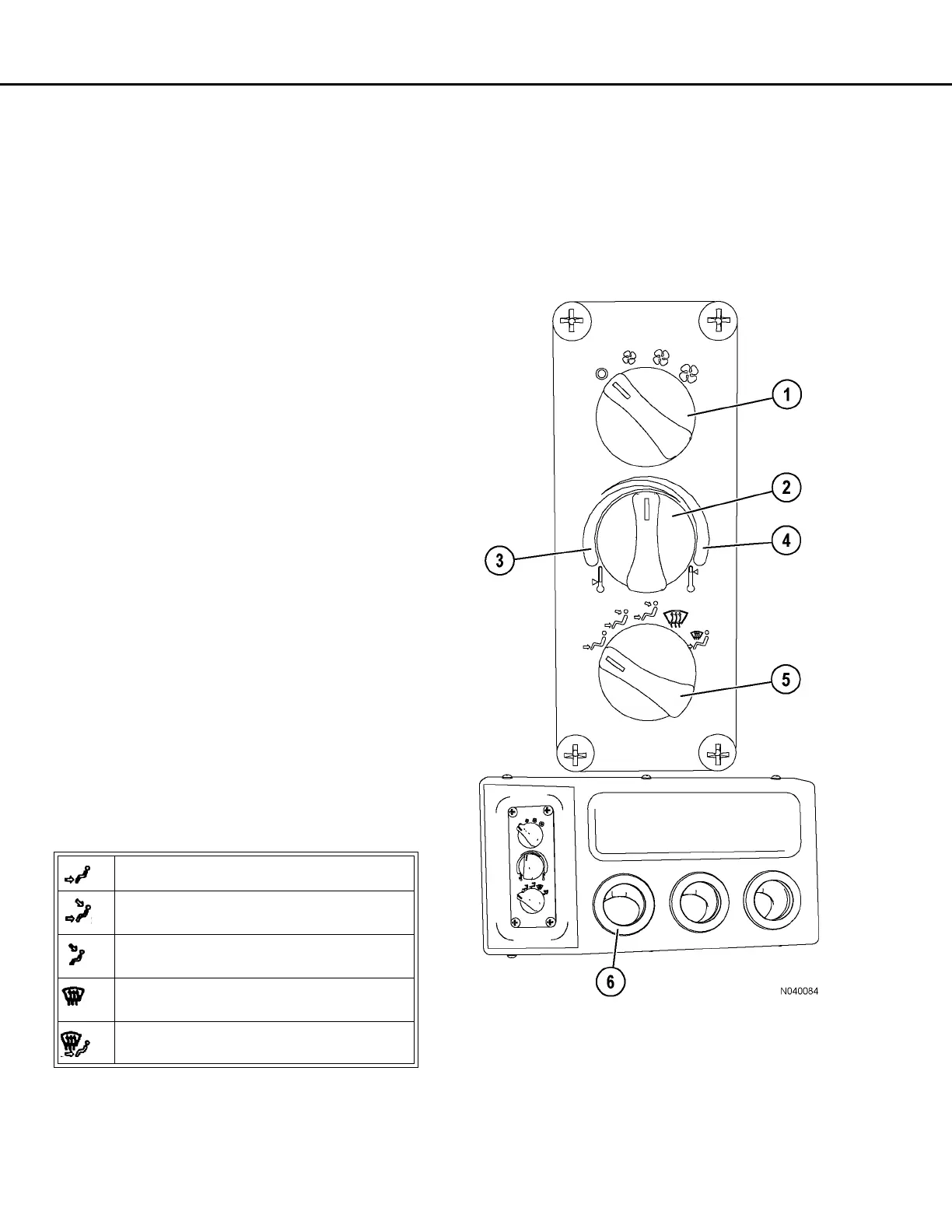
Fan Speed Control Knob
Fan speed control knob (1, Figure 32-7) is provided
to control the cab air fan motor. The fan motor is a 3-
speed motor (low, medium and high). Speeds are
selected by rotating the control knob clockwise to the
desired position. OFF is in the full counterclockwise
position. The control knob and the air conditioner
compressor switch must be switched ON for the air
conditioner to function.
Temperature Control Knob
Temperature control knob (2, Figure 32-7) allows the
operator to select a comfortable air temperature.
The control knob determines the operation of the air
conditioning and heater modes.
Rotating the control knob counterclockwise into blue
zone (3) will cause the A/C compressor to operate
and result in cooler air temperatures. The full
counterclockwise position is the coldest air setting.
Rotating the control knob clockwise into red zone (4)
will affect coolant flow through the heater core and
result in warmer air temperatures. The full clockwise
position is the warmest heater setting.
Air Flow Directional Knob
Air flow directional knob (5, Figure 32-7) controls the
direction of airflow as follows:
Heater/Air Conditioner Vents
Heater/air conditioner vents (6, Figure 32-7) may be
rotated 360°. There are three vents in the heater/air
conditioner compartment, four vents across the top of
the instrument panel, and one vent each in the RH
and LH instrument panels. There are also an
additional four vents under the instrument panel. Air
flow through the vents is controlled by manually
opening, closing or turning the louvers.
Provides airflow to the floor vents only.
Provides airflow to the upper vents and the
floor vents.
(Blue Icon) Provides dehumidified air to
the upper vents and the floor vents.
Defrost - Provides dehumidified air to the
upper vents only.
Defrost - Provides dehumidified air to the
upper vents and the floor vents.
FIGURE 32-7. A/C & HEATER CONTROLS
1. Fan Speed Control
Knob
2. Temperature Control
Knob
3. Blue Zone
4. Red Zone
5. Air Flow Directional
Knob
6. Vents
 Loading...