Automatic Lubrication System - Section 42 7/11 OM4213
Page 42-4
SYSTEM OPERATION
Normal Operation
1. During truck operation, the lubrication cycle
timer will energize the system at a preset time
interval.
2. The timer provides 24 VDC to energize the
pump solenoid valve (3, Figure 42-3), allowing
hydraulic oil provided by the truck steering
pump circuit to flow to the pump motor and
initiate a pumping cycle.
3. The hydraulic oil from the steering circuit is
directed through the pressure reducing valve
(4) and flow control valve (6) before entering the
motor. Pump pressure can be read on optional
pressure gauge (5) mounted on the manifold.
4. With oil flowing into the hydraulic motor, the
grease pump will operate, pumping grease from
the reservoir to the injectors (13), through a
check valve (10) and to the vent valve (11).
5. During this period, the injectors will meter the
appropriate amount of grease to each
lubrication point.
6. When grease pressure reaches pressure switch
(18, Figure 42-2) setting, the switch contacts
will close and energize the relay RB7-K5,
removing power from the hydraulic motor/pump
solenoid and the pump will stop. The relay will
remain energized until grease pressure drops
(pressure switch opens again) and the timer
turns off.
7. After the pump solenoid valve is de-energized,
hydraulic pressure in the manifold drops and
vent valve (11, Figure 42-3) will open, releasing
grease pressure in the lines to the injector
banks. When this occurs, the injectors are then
able to recharge for the next lubrication cycle.
8. The system will remain at rest until the
lubrication cycle timer turns on and initiates a
new grease cycle.
9. During the normal lubrication cycle, if grease
pressure fails to reach 13 790 kPa (2,000 psi)
within 120 seconds at the pressure switch
located on the rear axle housing, an amber
indicator light will illuminate on the overhead
panel.
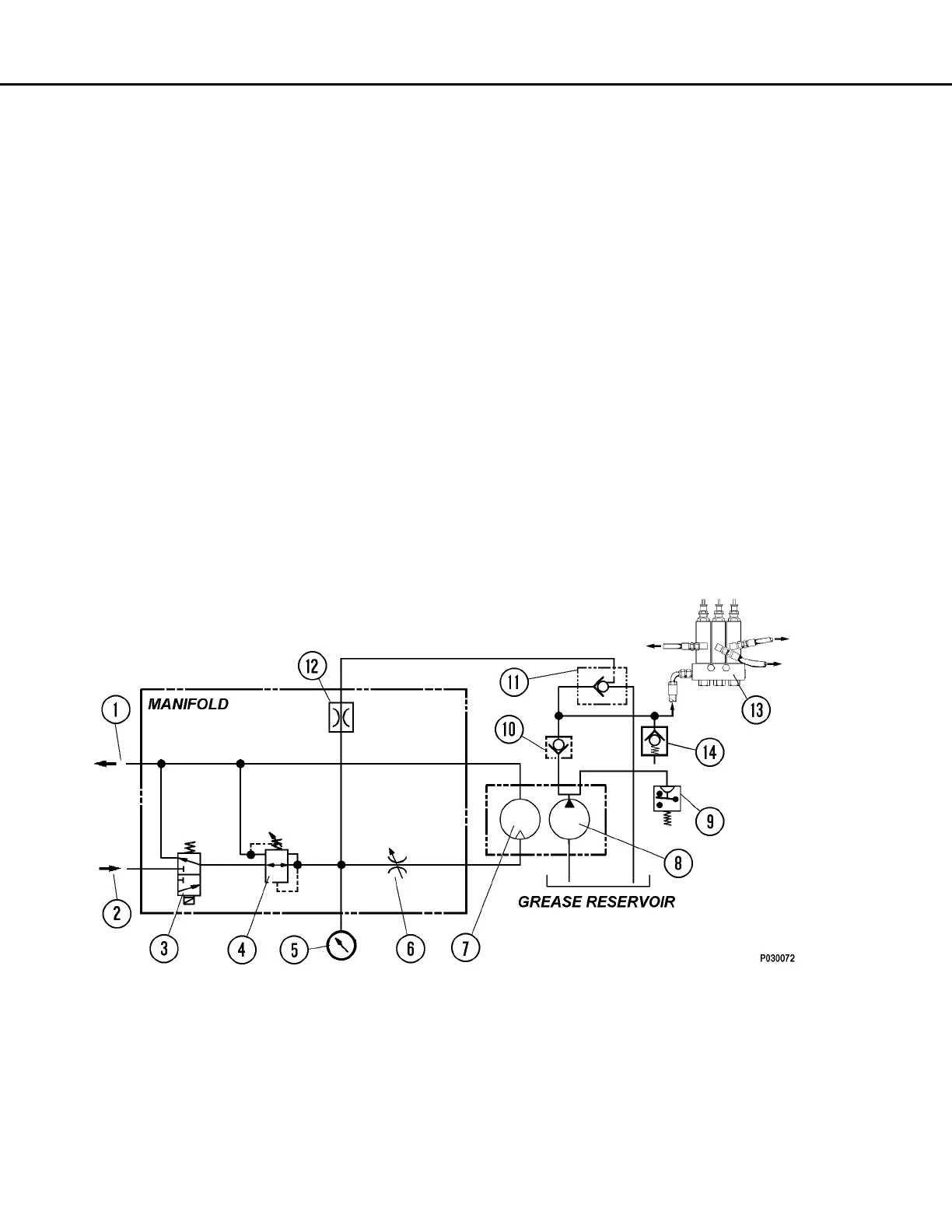
FIGURE 42-3. HYDRAULIC SCHEMATIC
1. Hydraulic Oil Return
2. Hydraulic Oil Supply
3. Solenoid Valve
4. Pressure Reducing Valve
5. Pressure Gauge
6. Flow Control Valve
7. Hydraulic Motor
8. Grease Pump
9. Pressure Switch (N.O.)
10. Check Valve
11. Vent Valve
12. Orifice
13. Injector Bank
14. Relief Valve
 Loading...