Operator Cab And Controls - Section 32 8/11 OM3245
Page 32-6
CENTER CONSOLE
Directional Control Lever
Directional lever (2, Figure 32-3) is mounted on the
console to the right of the operator's seat. It is a four
position lever that controls the park, reverse, neutral
and forward movement of the truck.
Before moving the directional control lever, apply the
service brakes to completely stop the truck. Depress
the button on the side to release the detent lock, then
move the control lever to the desired position. When
the control lever is in the center N position, it is in
NEUTRAL. When the control lever is in the P
position, it is in PARK, and the parking brake will be
applied. The parking brake is spring applied and
hydraulically released. It is designed to hold the truck
stationary when the engine is off and the key switch
is turned OFF. The truck must be completely stopped
before moving the control lever to PARK, or damage
may occur to the parking brake.
When the key switch is ON, and the control lever is in
PARK, parking brake indicator light (A3, Figure 32-8)
in the overhead panel will be illuminated.
The directional control lever must be in PARK to
start the engine.
NOTE: Do not move the directional control lever to
the PARK position at the shovel or dump site.
The operator can select FORWARD drive by moving
the lever to the F position.
The operator can select REVERSE drive by moving
the lever to the R position. Do not allow the control
lever to travel too far and go into the PARK position
when REVERSE is desired.
NOTE: The truck must be completely stopped before
the control lever is moved to a drive position or into
PARK. A fault will be recorded if the control lever is
placed into the PARK position while the truck is still
moving.
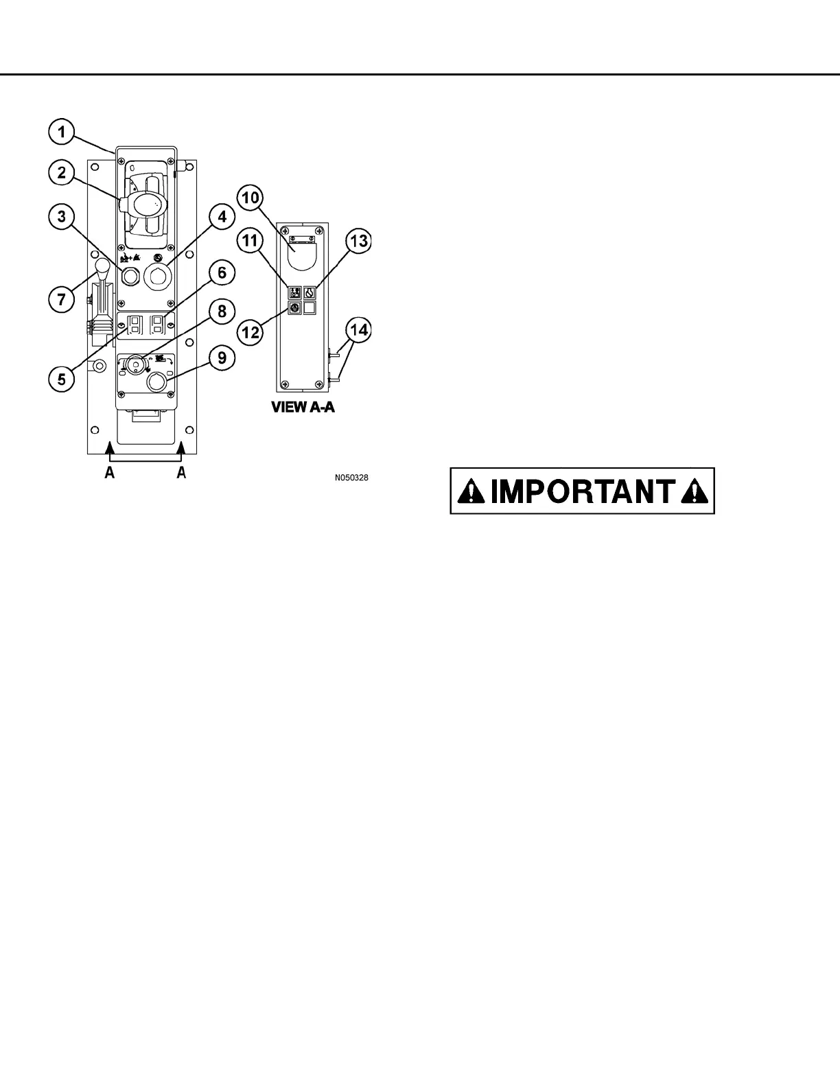
FIGURE 32-3. CENTER CONSOLE
1. Center Console
2. Directional Control Lever
3. Override/Fault Reset Switch
4. Engine Shutdown Switch
5. L.H. Window Control Switch
6. R.H. Window Control Switch
7. Hoist Control Lever
8. Retarder Speed Control Dial
9. Retarder Speed Control Switch
10. Data Store Button
11. KOMTRAX Plus Snapshot In Progress Light
12. Link Energized Light (red)
13. Service Engine Light (blue)
14. 12V Auxiliary Power Outlets
 Loading...