OM2042 7/11 Safety - Section 20
Page 20-19
Manual DC Link Capacitor Discharge Procedure
Follow any and all local and site specific procedures
and requirements for working on off-highway mining
equipment.
Verify that:
• The engine is off and the parking brake is on.
• The generator field is cut out via GF cutout switch
(2, Figure 20-4) in the low voltage area of the
control cabinet.
1. Apply control power for a minimum of 30 sec-
onds. Then, turn off control power using control
power switch (1) on the switch panel.
With control power on, an RP contactor closes
and discharges the DC link through the
retarding grids in less than 10 seconds.
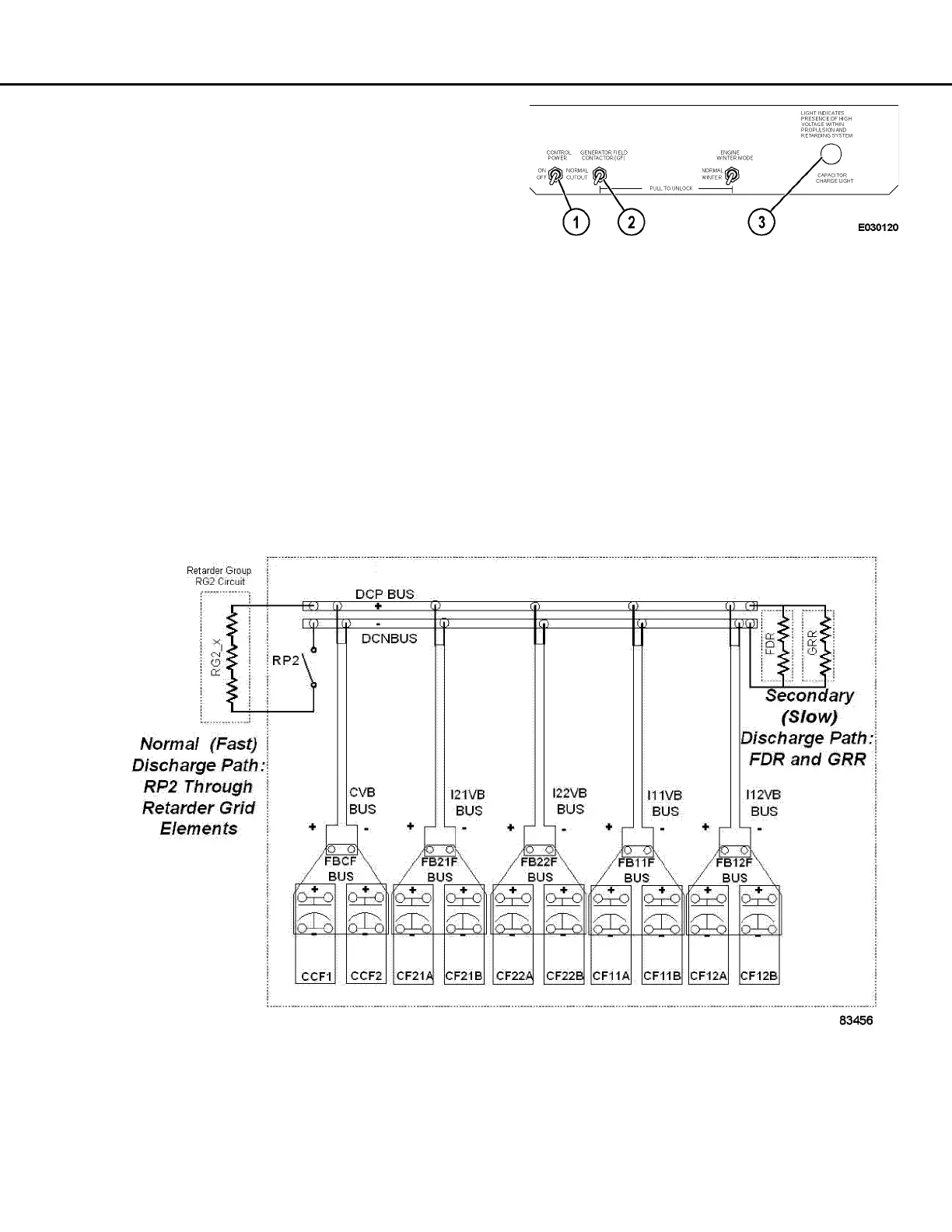
In most control cabinets, RP2 is the normal dis-
charge path. In groups containing an RP3 contactor,
RP2 and RP3 are alternated as the normal discharge
path. Refer to Figure 20-5.
FIGURE 20-4. INFORMATION DISPLAY PANEL
1. Control Power Switch
2. GF Cutout Switch
3. Capacitor Charge
Light
FIGURE 20-5. DISCHARGE PATHS
 Loading...