SEN04116-00 30 Testing and adjusting
4 PC130-8
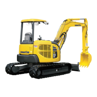
3. Pump controller
1) Slide the operator's seat and seat stand to
the forward end.
2) Remove the 5 mounting bolts and cool &
hot box (6).
a While removing the cool & hot box,
disconnect the drain hose.
3) Remove the 2 mounting bolts, 1 fastener,
and magazine box (7).
4) Remove the 3 mounting bolts and cover
(8).
5) Remove fuse box cover (9) and cover
(10).
a Since the underside of cover (10) is
clamped, pull it up.
6) Remove the 7 mounting bolts and cover
(11).
7) Connect the troubleshooting adapters to
connectors C01 and C02 of pump control-
ler (12).
a Install the adapters to only the wiring
harness side.
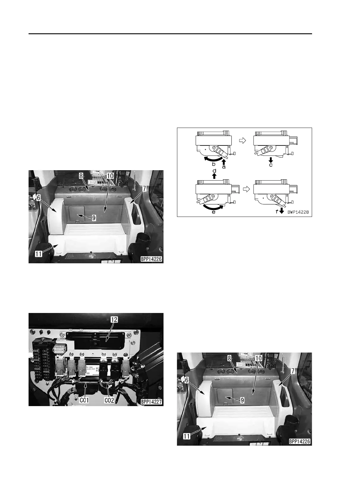
a The connectors of the pump control-
ler have a special locking mecha-
nism. Disconnect them according to
steps (a) – (c) and connect them
according to steps (d) – (f) as shown
below.
Disconnection: (a) Unlock – (b)
Slide lever – (c) Disconnect connec-
tor.
Connection: (d) Position connector –
(e) Slide lever – (f) Lock.
4. KOMTRAX communication module
1) Slide the operator's seat and seat stand to
the forward end.
2) Remove the 5 mounting bolts and cool &
hot box (6).
a While removing the cool & hot box,
disconnect the drain hose.
3) Remove the 2 mounting bolts, 1 fastener,
and magazine box (7).
4) Remove the 3 mounting bolts and cover
(8).
5) Remove fuse box cover (9) and cover
(10).
a Since the underside of cover (10) is
clamped, pull it up.
6) Remove the 7 mounting bolts and cover
(11).

 Loading...