SEN04120-03 40 Troubleshooting
28 PC130-8
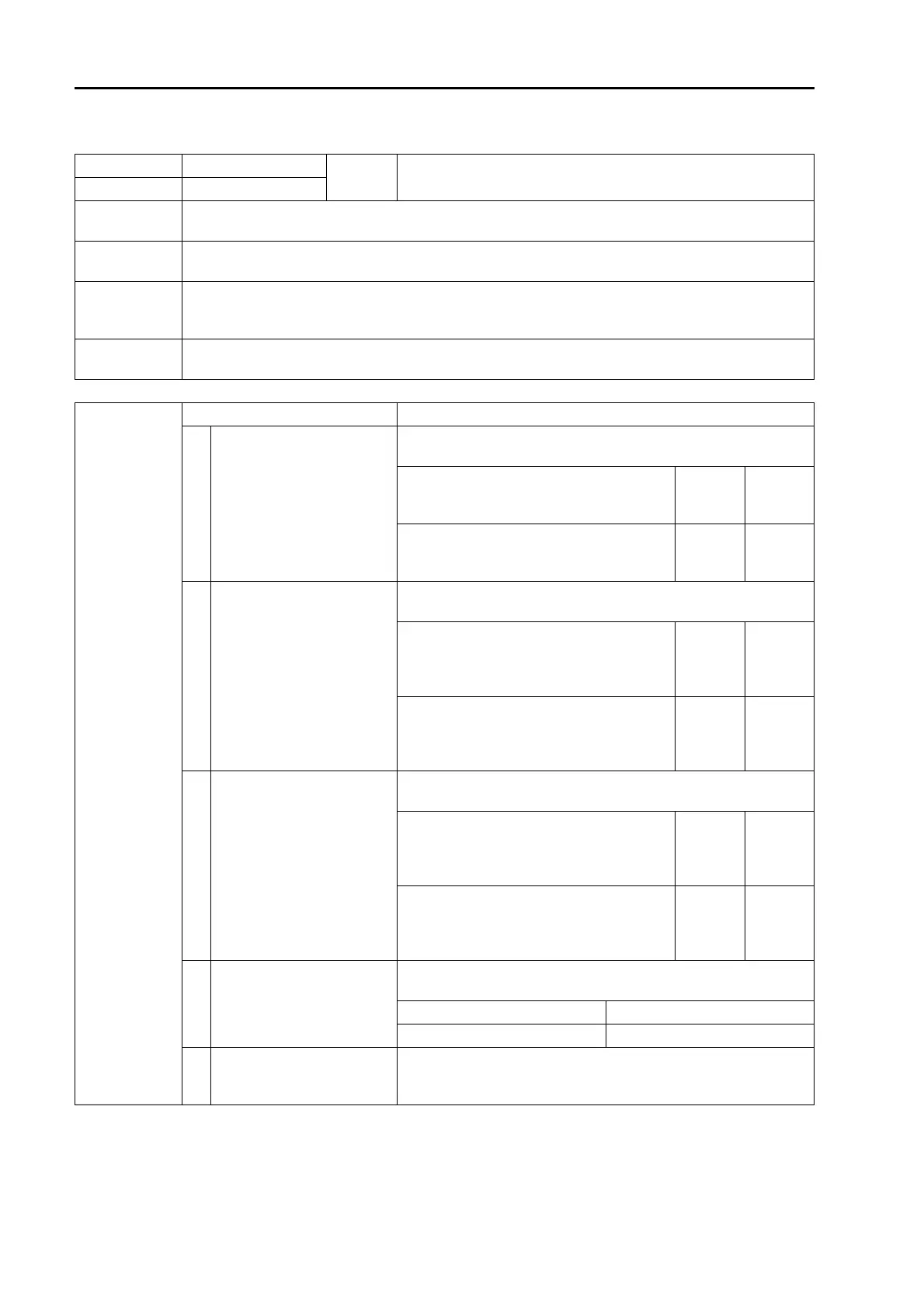
Failure code [CA1633] KOMNET datalink timeout error 1
User code Failure code
Trouble
KOMNET datalink timeout error
(Engine controller system)
E0E CA1633
Contents of
trouble
• Engine controller detected communication error in KOMNET communication circuit between pump
controller and machine monitor.
Action of
controller
• Continues operation in default mode.
• If cause of failure disappears, system resets itself.
Problem that
appears on
machine
• Information may not transmitted normally by KOMNET communication and machine may not oper-
ate normally. (Trouble phenomenon depends on failed section.)
Related
information
• Method of reproducing failure code: Turn starting switch ON.
Possible causes
and standard
value in normal
state
Cause Standard value in normal state/Remarks on troubleshooting
1
Disconnection in wiring har-
ness (Disconnection in wiring
or defective contact in con-
nector)
a Prepare with starting switch OFF, then carry out troubleshoot-
ing without turning starting switch ON.
Wiring harness between CM02 (female) (8),
(9) – CP01 (female) (45), – CE02 (female)
(1), – K02 (female) (A)
Resis-
tance
Max. 1 z
Wiring harness between CM02 (female)
(10) – CP01 (female) (64), – CE02 (female)
(21), – K02 (female) (B)
Resis-
tance
Max. 1 z
2
Ground fault in wiring har-
ness (Short circuit with GND
circuit)
a Prepare with starting switch OFF, then carry out troubleshoot-
ing without turning starting switch ON.
Wiring harness between CM02 (female) (8),
(9) – CP01 (female) (45), – CE02 (female)
(1), – K02 (female) (A), – N08 (male) (3) and
chassis ground
Resis-
tance
Min. 1 Mz
Wiring harness between CM02 (female)
(10) – CP01 (female) (64), – CE02 (female)
(21), – K02 (female) (B), – N08 (male) (10)
and chassis ground
Resis-
tance
Min. 1 Mz
3
Hot short (Short circuit with
24V circuit) in wiring harness
a Prepare with starting switch OFF, then turn starting switch ON
and carry out troubleshooting.
Wiring harness between CM02 (female) (8),
(9) – CP01 (female) (45), – CE02 (female)
(1), – K02 (female) (A), – N08 (male) (3) and
chassis ground
Voltage
Max.
5.5 V
Wiring harness between CM02 (female)
(10) – CP01 (female) (64), – CE02 (female)
(21), – K02 (female) (B), – N08 (male) (10)
and chassis ground
Voltage
Max.
5.5 V
4
Defective CAN terminal
resistance (Internal short cir-
cuit or disconnection)
a Prepare with starting switch OFF, then carry out troubleshoot-
ing without turning starting switch ON.
K02 (male) Resistance
Between (A) – (B) 120 ± 12
z
5
Defective engine controller
If causes 1 – 4 are not detected, engine controller may be defec-
tive. (Since trouble is in system, troubleshooting cannot be carried
out.)

 Loading...