SEN04130-01 50 Disassembly and assembly
16 PC130-8
Disassembly and assembly of
control valve assembly 1
Assembly
a In this section, only precautions for assembling
the control valve assembly are explained.
a The
port Nos. in the drawings refer to the port
Nos. of the hoses that are specified to be dis-
connected in "Removal and installation of con-
trol valve assembly".
a The
number in ( ) attached to each tightening
torque shown in the drawings indicates the
number of bolts, plugs, etc.
q Coat the sliding surfaces of the parts with
engine oil before assembling.
2 Mating face:
Gasket sealant (SEALEND 242 or equivalent)
q The tightening torque and precautions for each
part are as follows. (Random order)
q Installation of cover (1):
Tighten nuts (17) in the order of [1] – [4] in 3
tim
es.
3 1st time: 58.8 – 68.6 Nm {6 – 7 kgm}
2nd time:7
8.5 – 88.3 Nm {8 – 9 kgm}
3rd time: 9
8.1 – 113 Nm {10 – 11.5 kgm}
a Pro
jection of stud end from nut end: 0.5 – 3
mm
q Assembly of block (10)
Tighten bolts (18) in the order of [1] – [4] in 3
tim
es.
3 1st time: 19.6 – 29.4 Nm {2 – 3 kgm}
2nd time:3
9.2 – 49.0 Nm {4 – 5 kgm}
3rd time: 5
8.8 – 73.5 Nm {6 – 7.5 kgm}
[*1]
q When tightening or loosening a plug shown in
sections G-G, M-M, N-N and AA-AA, be sure to
keep the spool in the valve body.
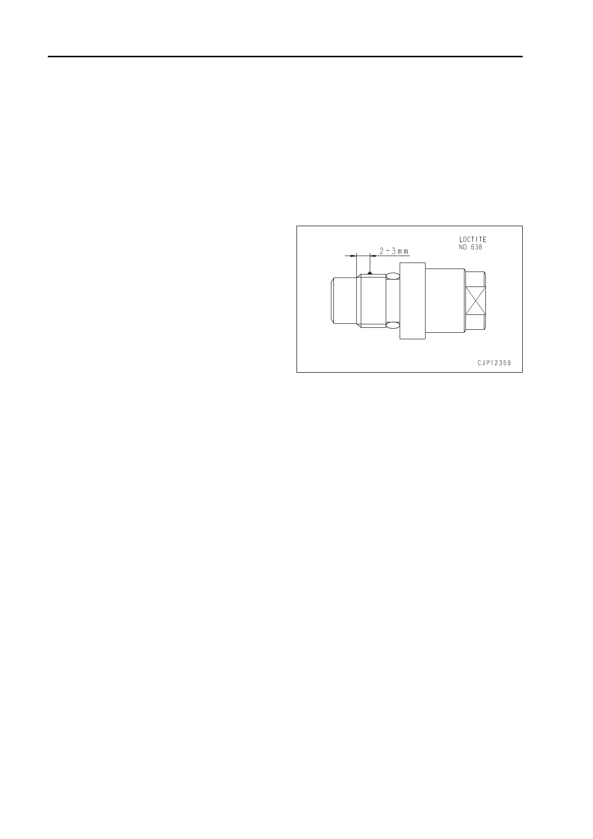
q When tightening each plug, apply a drop of
(approx. 0.02 g) LOCTITE (No. 638) to it.
a Tho
roughly degrease each plug and
female threaded part with denatured alco-
hol etc. and then dry them before tighten-
ing them. Do not apply pressure to them
for 2 hours after tightening them.
(Part to drop LOCTITE)

 Loading...