50 Disassembly and assembly SEN04130-01
PC130-8
39
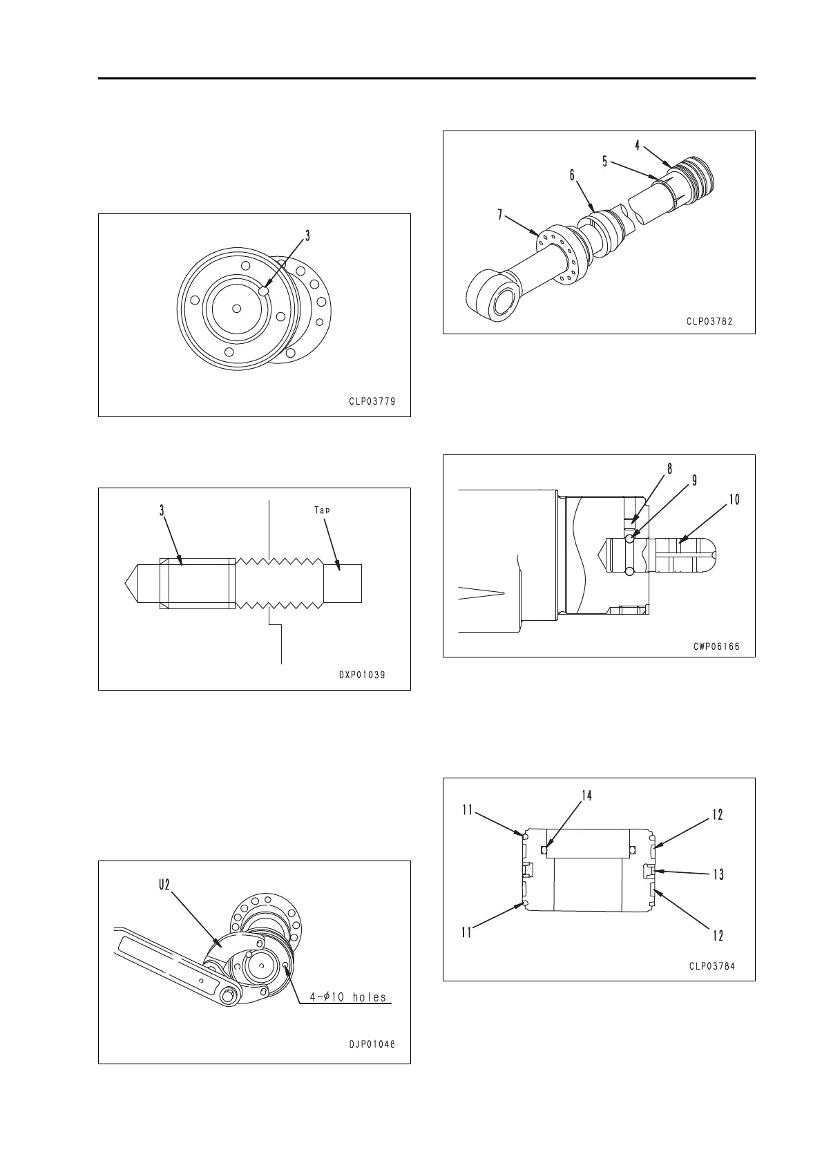
2] Remove piston assembly lock screw
(3).
Screw size
M12 x 1.75 pitch:
Boom, arm and blade
M10 x 1.5 pitch: Bucket
a If screw (3) is caulked too tightly to be
removed, force the screw in once and
then tap it to remove it.
3] Use tool U2 to remove piston assem-
bly (4).
q If tool (U2) is not used, use the
four drill holes (diameter = 10) to
loosen the piston assembly.
4] Remove plunger (5).
q Arm cylinder and boom cylinder.
5] Remove collar (6).
q Arm cylinder and boom cylinder.
6] Remove the head assembly (7).
7] Remove cap (8) to remove eleven
balls (9) and cushion plunger (10).
q For the arm cylinder only.
a Since
cap (8) is made of nylon,
tighten a screw into it and pull it
out with pliers.
2. Sub-disassembly of piston assembly
1) Remove ring (11).
2) Remove wear ring (12).
3) Remove piston ring (13).
4) Remove the O-ring and backup ring (14).

 Loading...