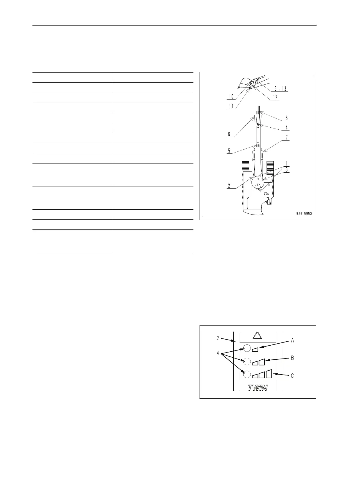
DIAGRAM OF AUTOMATIC GREASING POINTS
DIAGRAM OF AUTOMATIC GREASING POINTS
No. Part/Location
1 Swing circle
2 Boom cylinder foot pin
3 Boom foot pin
4 Boom cylinder rod end
5 Arm cylinder foot pin
6 Boom arm coupling
7 Arm cylinder rod end
8 Bucket cylinder foot pin
9 Bucket cylinder rod end (may
not be available with some
specifications)
10 Bucket - link coupling pin (may
not be available with some
specifications)
11 Arm-bucket coupling pin
12 Arm-link coupling pin
13 Link coupling pin (may not be
available with some specifica-
tions)
SYSTEM OPERATION
The system performs all operations automatically. When the starting switch is in the ON position the grease
pump will, at pre-defined intervals, supply measured quantities of grease to all the points connected to the sys-
tem.
Within 60 seconds after switching the starting switch to the ON position the in-cab display (2) shows the select-
ed greasing interval by flashing green lamp (4).
(A): Light Duty greasing interval
(B): Normal Duty greasing interval
(C): Heavy Duty greasing interval
CHANGING THE GREASE INTERVAL WITH THE IN-CAB DISPLAY
1.
Make sure the ignition is switched ON.
ATTACHMENTS AND OPTIONS AUTOMATIC GREASE SYSTEM
6-9

 Loading...