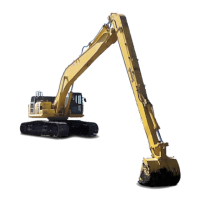
2-PIECE BOOM
GENERAL VIEW OF MACHINE FOR 2-PIECE BOOM
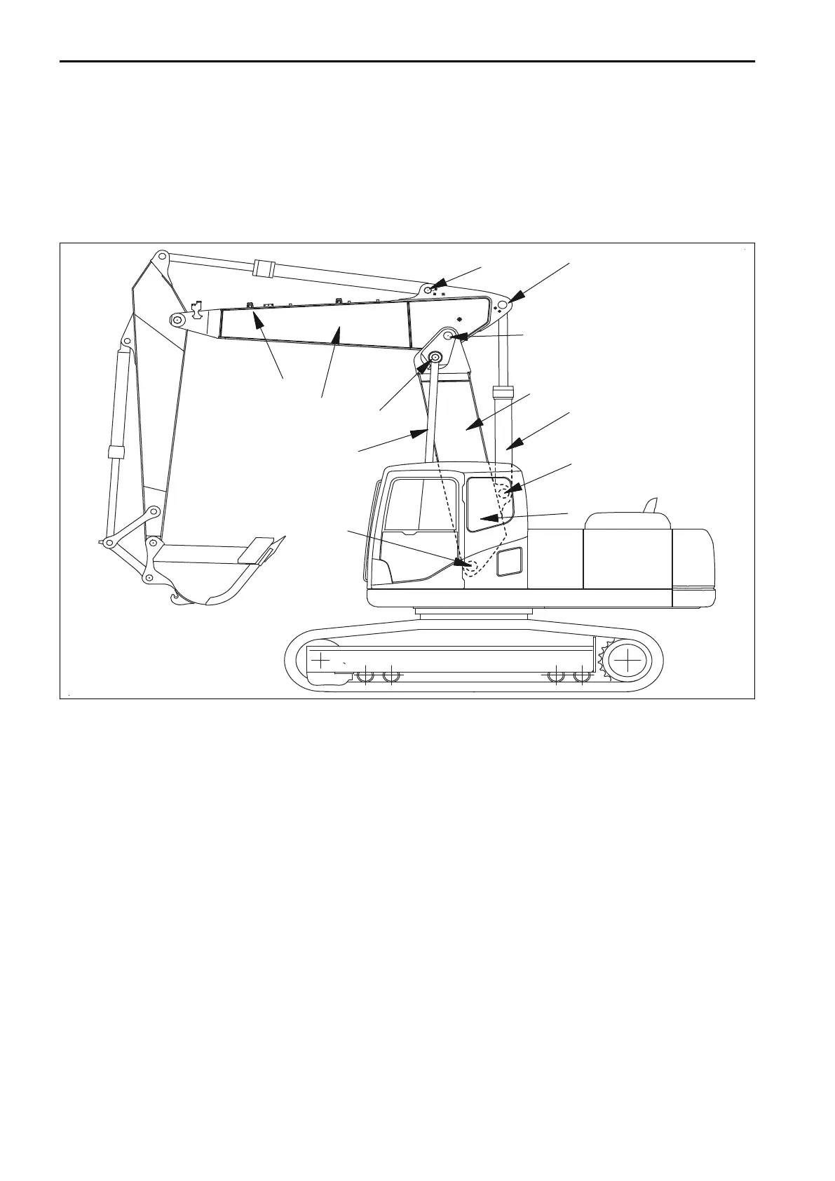
General View of Machine
The image below shows the layout of a 2-piece boom machine, including location of grease points (for first and
second booms only).
(1) Side of arm - 3 grease points located here for joints A,
B, and C
(4) First boom
(2) Second Boom (5) Top of boom foot - 5 grease points located here for
joints D, E and F
(3) First Boom Raise Cylinder (6) Second boom adjust cylinder
OPERATION
Explanation of Components
2-piece boom control pedal.
The control pedal to the left of the travel levers controls the operation of the second boom adjust cylinder. Press-
ing down on the front of the pedal pushes the second boom away from the cab, pressing down on the rear of
the pedal pulls the second boom towards the cab.
2-PIECE BOOM ATTACHMENTS AND OPTIONS
6-14

 Loading...