.
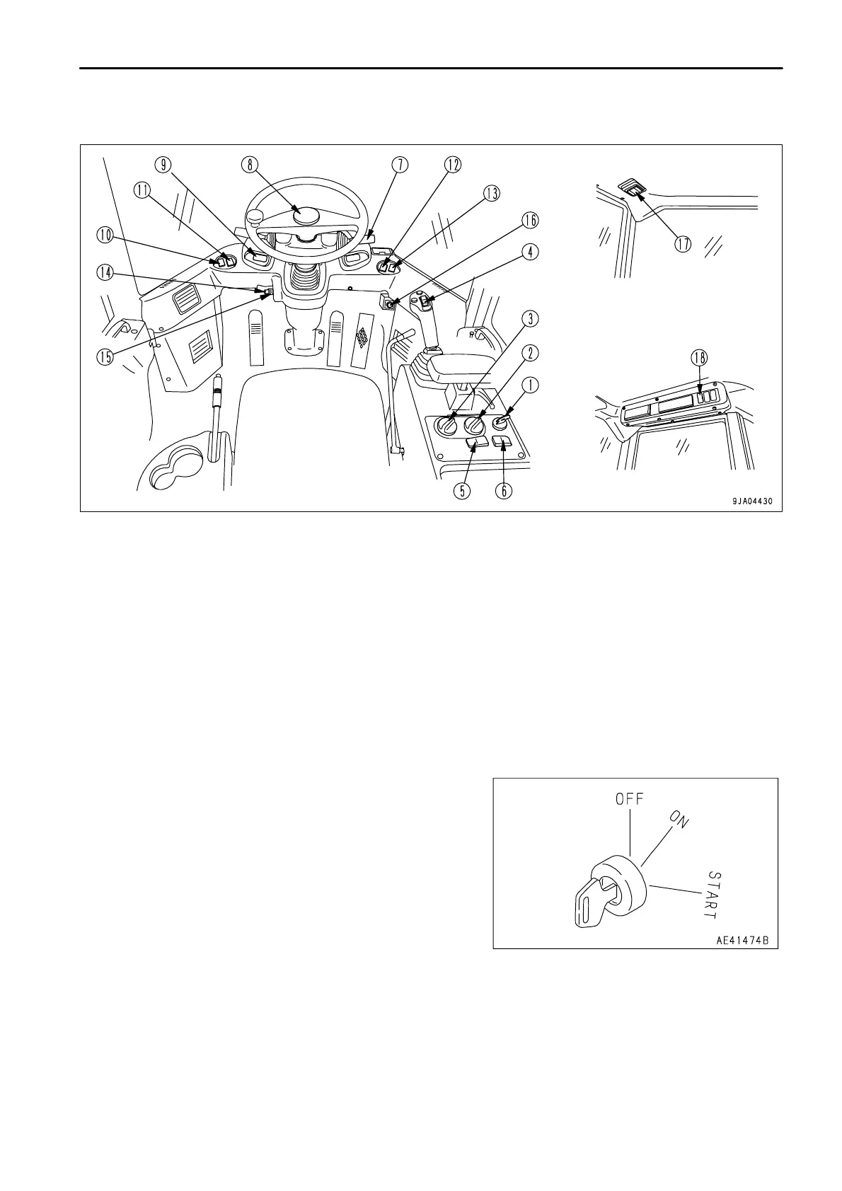
EXPLANATION OF COMPONENTS
(1) Starting switch
(2) Speed range selector switch
(3) Variable shift control switch
(4) Directional selector switch
(5) Directional selector actuation switch
(6) E.C.S.S. switch (if equipped)
(7) Lamp switch
(7) Turn signal lever
(7) Dimmer switch
(8) Horn button
(9) Hazard lamp switch
(10) Front working lamp switch
(11) Rear working lamp switch
(12) Monitor panel mode selector switch 1
(13) Monitor panel mode selector switch 2
(14) Front wiper switch
(15) Rear wiper switch
(16) Cigarette lighter
(17) Room lamp switch
(18) Rear heated wire glass switch
This switch (1) is used to start or stop the engine.
OFF position
In this position, it is possible to insert or remove the starting switch
key. All the electric system switches are off, and the engine will
stop.
ON position
In this position, electric current flows to the charging circuit, lamp
circuit, and accessory circuit.
Keep the starting switch key at the ON position while the engine is
running.
START position
This is the position to start the engine. Hold the key at this position while cranking. Release the key immediately
after the engine has been started. The key will return to the ON position when released.

 Loading...