Omega
14
7.5 Instructions for Replacing Subassemblies
7.5.1 Replacing the Shaft Seal
Proceed as described in section 8.1 and 8.2.
7.5.2 Replacing Casing Wear Rings and / or Impeller
Wear Rings
The impeller clearance
1)
clearance between impeller 234 and
casing wear ring 502 is given in the table below.
For impeller removal proceed as described in section 7.3,
”Dismantling”.
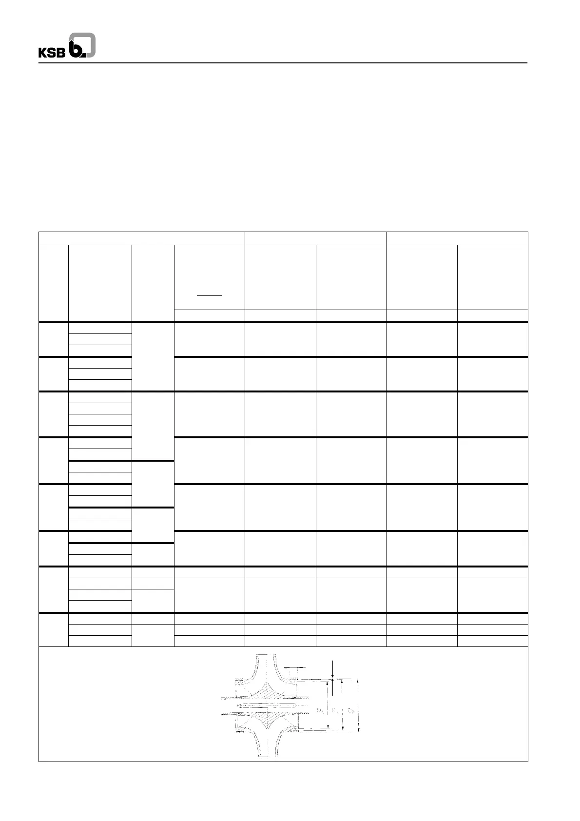
Impeller clearances and trim dimensions for impeller wear rings
After dismantling as described in section 7.3.2, the casing wear
rings (502) can be removed. When fitting the rings, ensure that
their bezels are on the outside (towards the bearing). The pins
(561.01) must be positioned as shown in the diagram below.
If the impeller has not been fitted with a wear ring at the factory,
and changing the casing wear ring alone does not achieve an-
ything close to the required impeller clearance (the impeller
neck is badly worn by clearance flows), the impeller neck must
be turned off on a lathe (contact KSB before doing so) and an
impeller wear ring fitted in addition (available as spare part).
Alternatively, a new impeller can be supplied at short notice.
Clearance (as--new) Dimensions of impeller wear ring
No. Pump
size
Shaft
unit
Nominal clea-
rance
(max. perm.)
D
2
-D
1
Min.
clearance
Smin
Max.
clearance
Smax
DW 2 D5 b
[mm] [mm] [mm] [mm] [mm]
1 80-210 0,3 0,15 0,2 134 r6 18
2 80-270 0,3 0,15 0,2 134 r6 18
3 80-370
0,3 0,15 0,2 134 r6 18
4 100-250
40
0,35 0,17 0,2 163 r6 22
5 100-310 0,35 0,17 0,2 163 r6 22
6 100-375 0,35 0,17 0,2 163 r6 22
7 125-230 0,35 0,18 0,23 178 r6 22
8 125-290 0,35 0,18 0,23 178 r6 22
9 125-365
0,35 0,18 0,23 178 r6 22
10 125-500
50
0,35 0,18 0,23 178 r6 22
11 150-290 0,45 0,22 0,26 210 r6 30
12 150-360 0,45 0,22 0,26 210 r6 30
13 150-460 0,45 0,22 0,26 210 r6 30
14 150-605
0,45 0,22 0,26 210 r6 30
15 200-320
60
0,5 0,24 0,28 243 r6 30
16 200-420 0,5 0,24 0,28 243 r6 30
17 200-520 0,5 0,24 0,28 243 r6 30
18 200-670
70
0,5 0,24 0,28 243 r6 30
19 250-370
0,5 0,24 0,28 276 r6 30
20 250-480
0,5 0,24 0,28 276 r6 30
21 250-600
80
0,5 0,24 0,28 276 r6 30
22 300-300 70 0,5 0,24 0,28 259 r6 30
23 300-435 80 0,6 0,29 0,35 313 r6 35
24 300-560
0,6 0,29 0,35 313 r6 35
25 300-700
90
0,6 0,29 0,35 313 r6 35
26 350-360 80 0,5 0,24 0,28 294 r6 35
27 350-430
0,6 0,32 0,37 333 r6 35
28 350-510
90
0,6 0,32 0,37 353 r6 35
b
S (min - max)

 Loading...