Omega
7
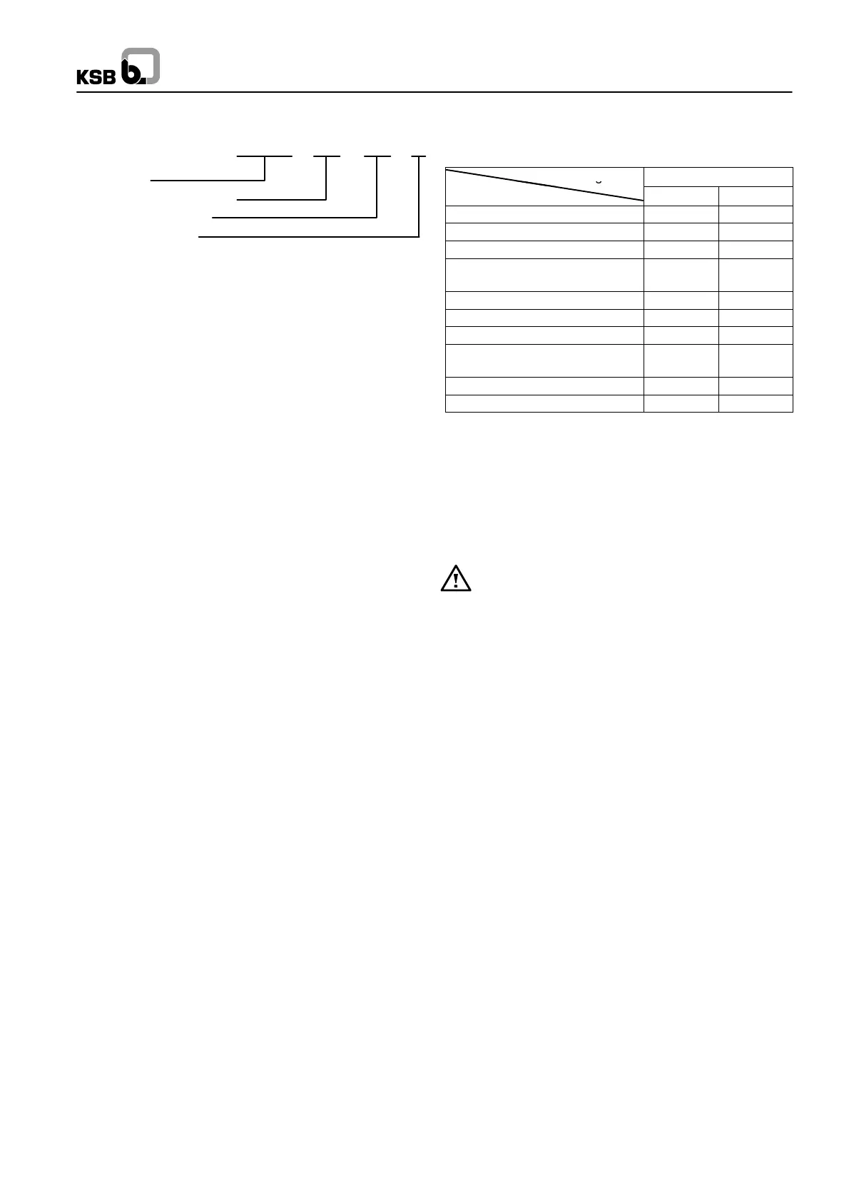
4.2 Designation
Omega XXX XXX X
Type series
Discharge nozzle DN mm
Nominal impeller dia.
Impeller type (A,B,C)
4.3 Design Details
4.3.1 Pump Casing
Axially split volute casing with replaceable casing wear rings.
Suction and discharge nozzles in lower half of casing are at the
same level (inline version).
4.3.2 Impeller
The double-- entry radial impeller is manufactured for the opera-
ting data provided in each case. Also with impeller wear rings,
if requested.
In double--entry radial impellers the axial thrust is largely balan-
ced.
4.3.3 Pump Shaft
The shaft is fully sealed against the liquid being pumped. Shaft--
protecting sleeves are fitted in the seal area.
4.3.4 Shaft Seal
The shaft seals at the drive end and non--drive end are gland
packings or mechanical seals, as requested.
4.3.5 Bearings and Lubrication
The pump is fitted with covered deep--groove ball bearings
which are grease--lubricated for life.
The fixed bearing at the non--drive end is located on a bush to
permit rapid changing without removing the rotor or upper half.
4.4 Types of Installation
The pump set is installed in configuration 3E -- horizontal instal-
lation, direct--coupled (see appendix).
4.5 Accessories (optional)
The following accessories are available:
Configuration Omega
Accessories Fig.0 3E
Motor -- -- x
1
)
Baseplate/baseframe -- -- x
1
)
Coupling and coupling guard -- -- x
1
)
Sealing and flushing water pi-
ping
x x
Set of pressure gauges x x
Cyclone separator with pipework x x
Vent valve (manual or automatic) x x
Temperature sensor for rolling
element bearings (PT 100)
x x
Signal transmitter for PT 100 x x
Drain line x x
2
) included in standard scope of supply
4.6 Dimensions and Weights
For dimensions and weights please refer to the tables in the ap-
pendix.
5 Installation at Site
5.1 Safety Regulations
Electrical equipment operated in ”zone 1” hazardous
locations must comply with the explosion protection
regulations. This is indicated on the motor rating pla-
te.
If the equipment is installed in hazardous locations, the applica-
ble local explosion protection regulations and the regulations of
the test c ertificate supplied with the equipment and issued by
the responsible approval authorities must be observed and
complied with.
The test certificate must be kept close to the location of opera-
tion for easy access (e.g. foreman’s office).
5.2 Checks to Be Carried out Prior to
Installation
All structural work required must have been prepared in accor-
dance with the dimensions and loads stated in the dimension
table / installation plan.
The concrete foundations shall have sufficient strength
(min. BN 25) to ensure safe and functional installation in
accordance with DIN 1045 or equivalent standards.
Make sure that the concrete foundation has set firmly before
placing the unit on it. Its surface shall be truly horizontal and
even.

 Loading...