a
1
a
2
n
1
5D
h
3
h
1
DN
1
b
1
n
3
n
4
n
2
DN
2
h
2
1M
1M
d
2
s
1
s
2
6B
s
d
3
5D 5D
Z
l
3
l
2
f
l
1
d
1
8B 8B
m
1
m
2
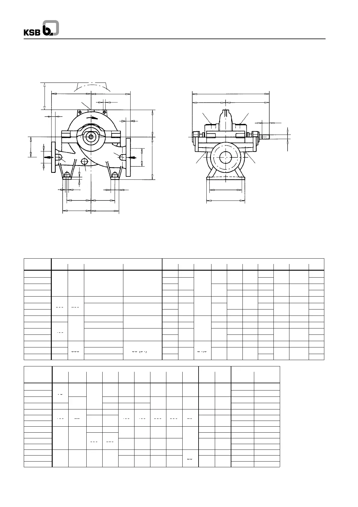
Flanges:
- All flanges designed as plate flanges
- flange thickness to ANSI
- Connect pipes without transmitting stresses or strains
Connections:
- 1M Pressure gauge G 1/2
- 5D Vent G 1/2
- 6B Drainage G 1/2
- 8B Leakage liq. drain G 3/4
Keyway and key
DIN 6885 sheet 1
Shaft diameter:
Tolerance h
6
to DIN 7155
Direction of rotation:
CLOCKWISE
Omega
62
Dimension tables Omega 200 -- 320 up to 350 -- 510
Fig. 0 N.B.: If the pump’s direction of rotation is
Direction of rotation: CLOCKWISE ANTI--CLOCKWISE, the position of
the suction and discharge nozzle is
reversed (mirror image).
Dimensions and weights All dimensions in mm
Pump
Flange dimensions Pump dimensions
Size DN
1
DN
2
s
1
s
2
a
1
a
2
d
3
f h
1
h
2
2)
h
3
l
2
l
3
z
2)
200-320 450 450
285
570
200-420
500
590 500 240
310
399 989
620
200-520
250 200 48 41
600
5
24,5
560 300 370
740
200-670 650 550
55
600 350 430
4
4
860
250-370 33 (51)
1)
32 (48)
1)
500 500 655
320 464 1119 640
250-480
300 250
550
12,5
355
710
250-600
5
4
650
55
7
630 350 415
5
5
45
830
300-300 350 36 (54)
1)
33 550 500 655 630 300 360 464 1119 720
300-435
38 (57)
1)
(51)
1)
650 550
730 670 350 365 515 1245 730
300-560
400
700
4,5
710 350 430
860
300-700
57 5
750
5
750 400 480
5
5
5
960
350-360 400 38 (57)
1)
650 550 730 670 350 410 515 1245 820
350-430 450
350
41 (60)
1)
36 (54)
1)
750
24,5
465
930
350-510 400
38 (57)
1)
700
5
75
4
420
5
5
5
840
Pump Foot dimensions Shaft
Weights [kg]
Size b
1
d
2
m
1
m
2
n
1
n
2
n
3
n
4
s d
1
l
1
Pump Water
fill
200-320
450 80
200-420
70
17,5
430 315 315 280 280 20 55 125
520 95
200-520
480
400 385 385
840 115
200-670 100
400 400 400
5
5
5
4
990 140
250-370 480 400 65 140 665 125
250-480
100 22
400 400 350 350 26
830 145
250-600
5
75
1215 180
300-300 480 400
65 140 630 100
300-435
4
4
5
5
75 160 905 190
300-560
600 520
1425 225
300-700
5
5 5
5 475 475
5
1690 275
350-360 400 400 350 350 75 160 865 160
350-430 100 22 600 520
26
1285 240
350-510
5
5 5
5 475 475
5
1395 290
1)
for casing material GGG--NiCrNb 202, JS 1030, 1.4517
2)
z = clearance above casing cover for dismantling of the rotor

 Loading...