Omega
35
Dimensions in mm
Pump
sizes
Impeller dimensions in mm Permissible nozzle Mass moments of
inertia
J
Permissi-
ble opera-
ting
pressure
Permissi-
ble test
pressure
free passage
± 10 %
max. diameter Clearances forces
in N
moments
in Nm
(without coupling)
in kgm
2
in bar in bar
A B C A B C A B C F
x
,F
y
,F
z
1); 3)
M
x
,M
y
,M
z
1); 3)
without
water
with
water
1) 2) 1) 2)
250-370 39 27 20 390 390 390 0.5 0.5 0,5 4000 2750 0.721 1.225 10 25 15 37.5
250-480 30 20 -- 478 478 -- 0.5 0.5 -- 4000 2750 0.956 1.625 16 25 24 37.5
250-600 23 16 -- 622 622 -- 0.5 0.5 -- 4000 2750 2.206 3.750 24 25 28 37.5
300-300 39 27 -- 323 323 -- 0.5 0.5 -- 4000 3000 0.571 0.800 10 25 15 37.5
300-435 45 32 30 450 450 450 0.6 0.6 0,6 4000 3000 1.785 2.500 10 25 15 37.5
300-560 35 23 -- 553 553 -- 0.6 0.6 -- 5000 3000 2.411 3.375 16 25 24 37.5
300-700 26 18 -- 719 719 -- 0.6 0.6 -- 5000 3000 6.346 8.250 24 25 28 37.5
350-360 39 27 -- 373 373 -- 0.5 0.5 -- 5000 3000 1.116 1.563 10 25 15 37.5
350-430 57 40 -- 430 430 -- 0.6 0.6 -- 5000 3000 2.232 3.125 10 25 15 37.5
350-510 52 36 35 518 518 518 0.6 0,6 0,6 5000 3000 3.393 4.750 10 25 15 37.5
1
) Casing material JL 1040 and GGG-NiCrNb 20 2
2
) Casing material JS 1030 and 1.4517
3
) Casing material JS 1030; 1,4--times the given value
4
) Casing material 1.4517; 1,9--times the given value
11 Trouble--Shooting
11.1 General
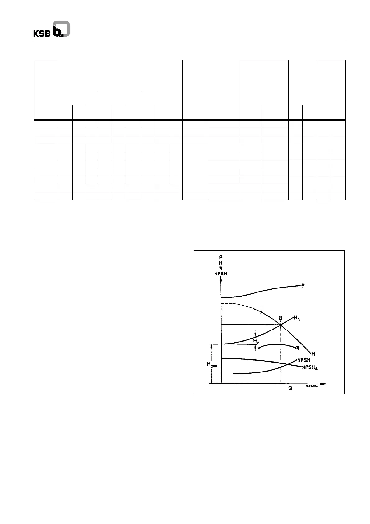
The diagram opposite is to facilitate understanding of the cau-
ses of faults and their remedies as indicated in the trouble--
shooting table.
The cause of many operating faults on pumps is often hydrau-
lic. The hydraulic behavior of a pump is illustrated by its charac -
teristic curves H, P, Eta and NPSH in combination with the plant
characteristic curves HA and NPSHA.The operating point B is
where the system curve HA and the characteristic curve H inter-
sect. Consult the manufacturer if the cause of a fault is unclear.
Power
Head
Efficiency
Operating Limit
Capacity

 Loading...