MAINTENANCE WORK ON CHASSIS AND ENGINE 83
11.98Adjusting the basic position of the clutch lever
B00001-11
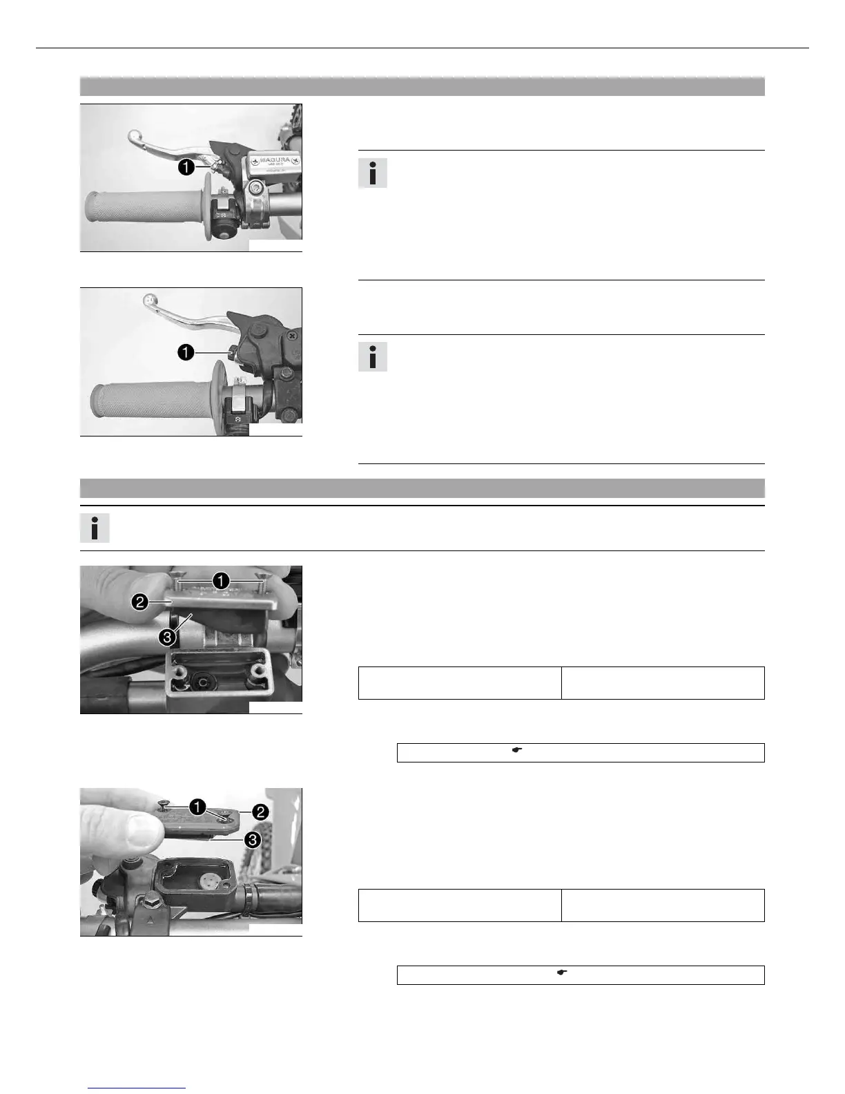
(All 125/150/200 models)
– Adjust the basic setting of the clutch lever to your hand size by turning adjust-
ing screw .
Info
Turn the adjusting screw counterclockwise to increase the distance
between the clutch lever and the handlebar.
Turn the adjusting screw clockwise to decrease the distance between
the clutch lever and the handlebar.
The range of adjustment is limited.
Turn the adjusting screw by hand only, and do not apply any force.
Do not make any adjustments while riding!
B00009-11
(All 250/300 models)
– Adjust the basic setting of the clutch lever to your hand size by turning adjust-
ing screw .
Info
Turn the adjusting screw counterclockwise to decrease the distance
between the clutch lever and the handlebar.
Turn the adjusting screw clockwise to increase the distance between the
clutch lever and the handlebar.
The range of adjustment is limited.
Turn the adjusting screw by hand only, and do not apply any force.
Do not make any adjustments while riding!
11.99Checking the fluid level of the hydraulic clutch
Info
The fluid level rises with increasing wear of the clutch lining discs.
400245-10
(All 125/150/200 models)
– Move the clutch fluid reservoir mounted on the handlebar to a horizontal posi-
tion.
– Remove screws .
– Remove cover with membrane .
– Check the fluid level.
Fluid level under top edge of con-
tainer
4 mm (0.16 in)
» If the level of the fluid does not meet specifications:
– Correct the fluid level of the hydraulic clutch.
Hydraulic fluid (15) ( p. 130)
– Position the cover with the membrane. Mount and tighten the screws.
B00040-10
(All 250/300 models)
– Move the clutch fluid reservoir mounted on the handlebar to a horizontal posi-
tion.
– Remove screws .
– Remove cover with membrane .
– Check the fluid level.
Fluid level under top edge of con-
tainer
4 mm (0.16 in)
» If the level of the fluid does not meet specifications:
– Correct the fluid level of the hydraulic clutch.
Brake fluid DOT 4 / DOT 5.1 ( p. 130)
– Position the cover with the membrane. Mount and tighten the screws.
 Loading...