 Loading...
Do you have a question about the Kubota B1700 and is the answer not in the manual?
| Engine Type | Diesel |
|---|---|
| Engine Power | 17 hp |
| Cylinders | 3 |
| Transmission | Gear |
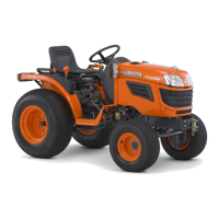
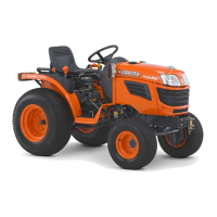
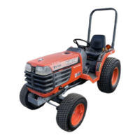
| Type | Compact Utility Tractor |
| Transmission Gears | 6 forward and 2 reverse |
| PTO Speed | 540 rpm |
| Hydraulic System Type | Open center |
Items to check before starting the tractor to prevent trouble.
Procedure for draining and refilling engine oil, including capacity.
Procedure for replacing the engine oil filter cartridge.
Procedure for testing safety switches related to engine starting.
Actions to take in case of engine overheating.
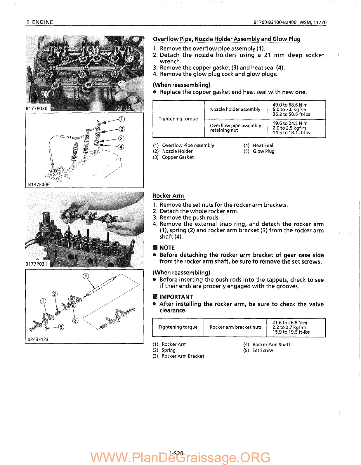
Procedure for checking engine valve clearance.
Procedure for flushing and changing coolant, including anti-freeze.
Overview of the lubricating system components and oil flow.
Troubleshooting chart for hydrostatic transmission issues.
Troubleshooting for noise from the clutch housing.
Troubleshooting for noise and gear slip issues in the transmission case.
Troubleshooting for noise, lock issues, and pedal return in the differential case.
Procedures for servicing the connecting rod and piston assembly.
Procedures for checking injection timing and fuel tightness.
Procedures for checking nozzle injection pressure and spraying condition.
Procedures for checking compression pressure and top clearance.
Procedure for checking cylinder head surface flatness.
Procedure for detecting flaws in the cylinder head.
Procedure for measuring cylinder wear.
Procedure for boring and finishing the cylinder inner wall.
Procedure for measuring engine oil pressure at idle and rated speeds.
Procedure for inspecting and adjusting injection pump timing.
Explanation of HST operation when the speed control pedal is in neutral.
Explanation of HST operation in forward mode.
Explanation of HST operation in reverse mode.