HYDRAULIC UNIT52
A If the implement control valve has a relief valve, the
tank port flow from implement should be connected to
the port located on the right hand side of transmission
case.
DUAL REMOTE HYDRAULIC CONTROL
SYSTEM
The tractor is equipped with the double-acting 2-segment
hydraulic control valve for the front loader.
To apply the hydraulic power take-off for general
attachments, keep the following point in mind.
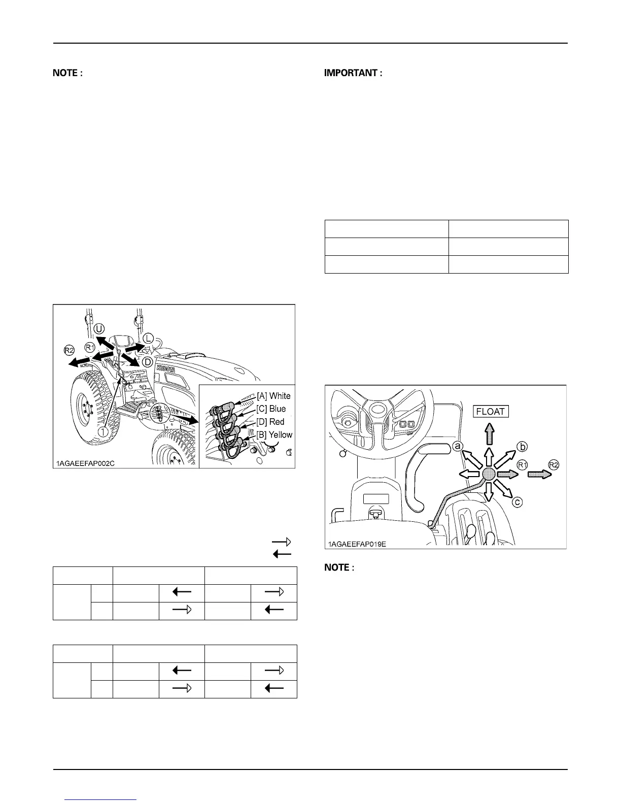
BControl Lever and Hydraulic Hose
Connections
Connect the control lever in its specified direction and the
hydraulic hoses to their specified ports.
To avoid damage of the attachments:
A Do not connect attachments through the hydraulic
motor to the [C] and [D] ports. If the control lever is
moved to the Regeneration position (R1), the seals on
the hydraulic motor will be damaged.
A This control valve is provided with the Regeneration
position. When the [C] and [D] ports are used to take
off hydraulic power for the hydraulic cylinder, be sure
to connect the [C] port to the "Head-End" side port of
the hydraulic cylinder.
A Make the following connections when using this valve
to take off hydraulic power for the hydraulic cylinder.
BLoader / Remote Control Valve Lever
1. Before moving the lever, make sure that the hydraulic
hoses for attachments are connected.
2. Move the lever diagonally (a, b, c shown in the figure),
and the first and second segments can be controlled
simultaneously.
A Move the lever to the "FLOAT" position, and it will be
held there by the detent mechanism. To use the valve
as a floating valve with detents, connect the hydraulic
hoses to ports [A] and [B].
A When taking off hydraulic power from port [D], the flow
rate can be adjusted in 2 stages with the lever.
The flow rate is high at position (R1) and low at
position (R2). Move the lever to position (R1) or (R2)
depending on the attachment in use.
(1) Loader / Remote control valve lever (R) "RIGHT"
(L) "LEFT"
(U) "UP"
(D) "DOWN"
Pressure
Returning
Hydraulic outlet ports of first segment
Lever UP DOWN
Port
[A] In Out
[B] Out In
Hydraulic outlet ports of second segment
Lever RIGHT LEFT
Port
[C] In Out
[D] Out In
Colored Coupler Hydraulic Cylinder port
[B: Yellow], [C: Blue] Head-End side
[A: White], [D: Red] Rod-End side

 Loading...


