U20-3, U25-3 WSM Electrical system (Service section)
V-S-20
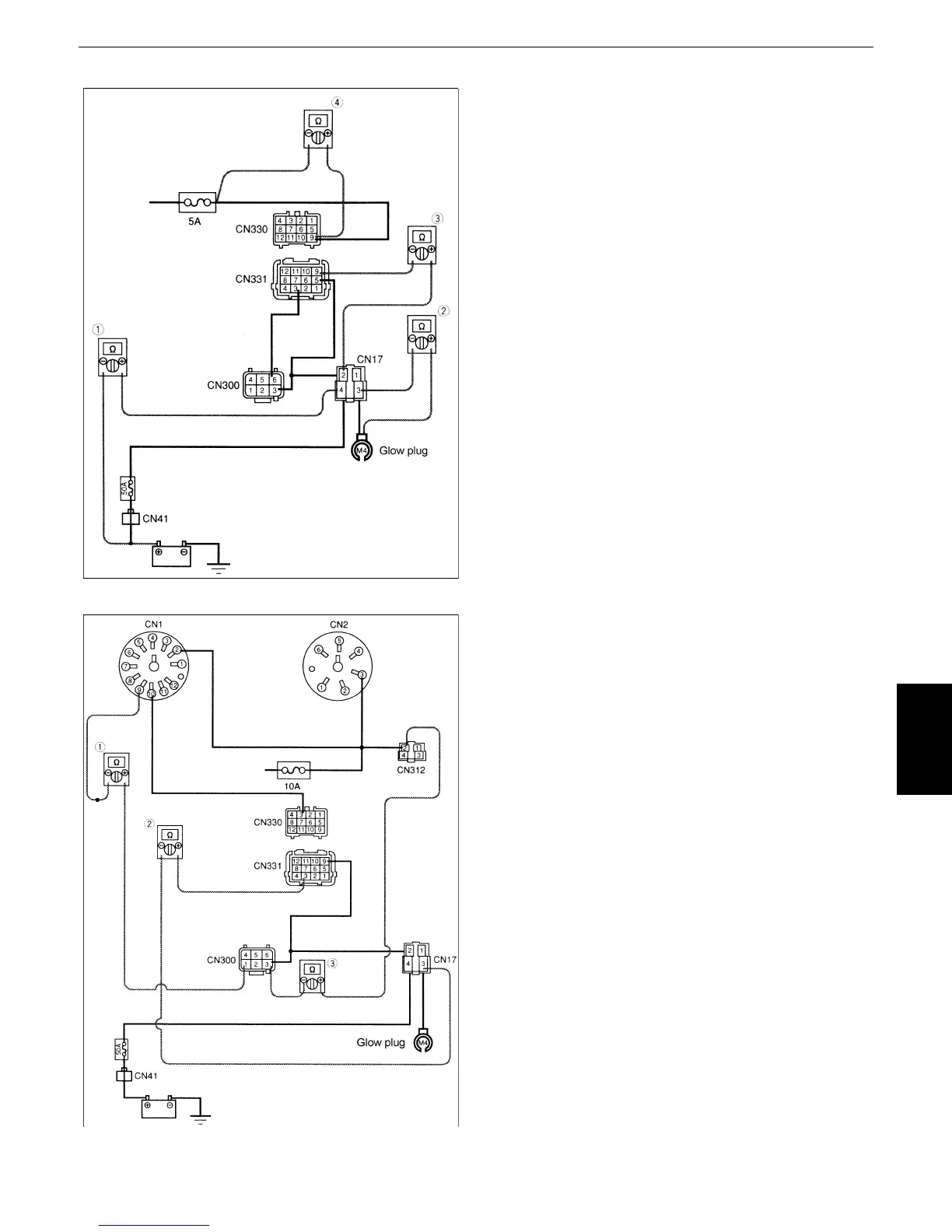
Fig.19-1
Fig.19-2
7. Continuity check
2
Key switch: OFF
2
Disconnect the coupler.
(1)Check for continuity between the battery ({)
and glow relay coupler CN17-(4).
(2)Check for continuity between the glow plug
and glow relay coupler CN17-(3).
(3)Check for continuity between the glow relay
coupler CN17-(2) and coupler CN331-(9).
(4)Check for continuity between the 5A fuse
and coupler CN330-(9).
8. Continuity check (Fig.19-2)
2 Key switch: OFF
2 Disconnect the coupler.
(1)Check for continuity between the meter
coupler CN1-(9) and glow control coupler
CN300-(3).
(2)Check for continuity between the coupler
CN331-(3) and glow relay coupler CN17-(3).
(3)Check for continuity between the
disconnection check relay coupler CN312-
(2) and glow control coupler CN300-(3).

 Loading...