Home
Kubota
Excavators
U20-3
Kubota U20-3 User Manual
5
of 1
of 1 rating
508 pages
Give review
Manual
Specs
To Next Page
To Next Page
To Previous Page
To Previous Page
Loading...
U20-3, U2
5-3 WSM
Machi
ne body (Se
rvice se
ction)
II
-S-24
2)
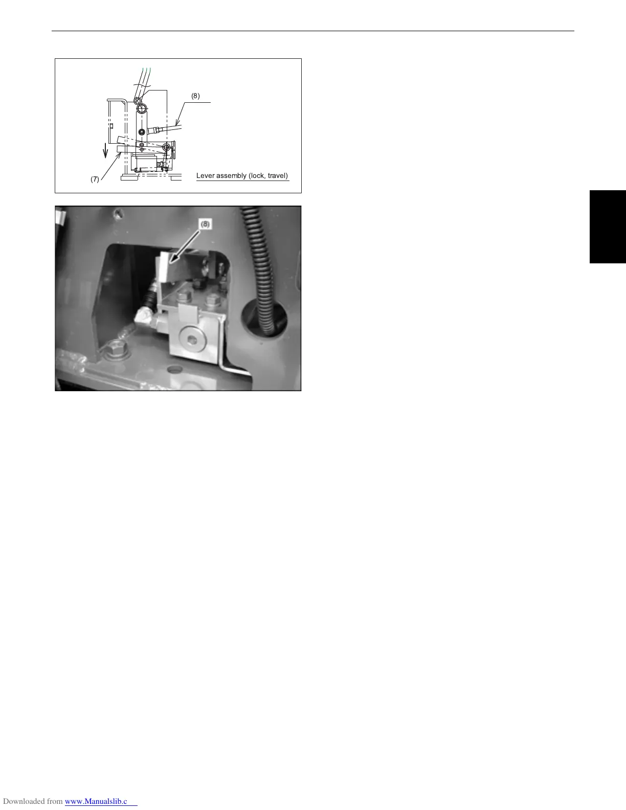
Check item
s after setup
Make sure
the valv
e spool
works a
ll over
the
stroke.
Make sure
the valv
e spool
moves smoothly
.
Lock the s
topper
bolt and nu
t tight
enough.
Lever
assembly
(lock,
travel)
(7)
(8)
72
74
Table of Contents
Table of Contents
3
A. Body and Engine Identification Marks
7
Engine Serial Number
7
Machine Serial Number
7
Inspecting Equipment and Tools
8
Precautions for Disassembly and Reassembly
9
Safety Measures before Starting Work
8
Safety Measures During Work
8
Safety Precautions for Servicing, Disassembly and Reassembly
8
Acceptance Inspection
9
Cleaning
9
Preparation for Disassembly
9
Essential Adhesives
10
Important Inspection Items after Reassembling
10
Important Safety Process and Critical Functional Process
10
Items for Servicing
11
Locking Adhesive
11
Servicing Fundamentals
11
Precautions in Tightening Hoses and Pipes
12
(Floating Seal
13
General Precautions
13
O-Ring, Oil Seal, Circlip and Roll Pin
13
Mounting the Circlip
14
Tapping the Roll Pin (Spring Pin)
14
Hydraulic Hose
15
Piping
15
Precautions in Tightening the Bolts and Nuts
15
Hose Screw
16
Joint Bodies
16
Metric Size Hose
16
Nuts for Piping
17
Tightening Torque Table for Hose Clamp (Screw Type)
17
Tightening Torque of Bolts and Nuts
18
Types and Materials of Bolts and Nuts
18
Connecting with the Valve
19
Washer-Equipped Elbow
19
Machine Quality Specifications
20
Maintenance Intervals Chart
28
Changing and Filling up of Hydraulic Oil
29
Changing the Return Filter and Oil
29
Hydraulic Oil Check for Machines with Hydraulic Breakers
29
List of Important Parts
30
Periodic Replacement of Important Parts
30
Machine Body (Mechanism Section)
31
Specifications
33
Main Dimensions
34
Bucket
35
Components Interchangeability
35
Control Linkage
36
Machine Structure
36
Traveling Lever
36
Accelerator Lever
37
Dozer Lever
37
Service Port Pedal
38
Swing Pedal
38
Retractable Track Lever
39
Engine Mount
40
Tension Spring
42
Undercarriage
42
Upper Roller and Track Roller
42
Fixed Undercarriage
43
Interchangeability between Rubber and Iron Crawler
43
Retractable Undercarriage (U20-3 Only)
44
Retractable Undercarriage
45
Rubber Crawler
46
Steel Crawler
47
Machine Body (Service Section)
49
Machine Weight
51
Machine Specifications
52
Lever Stroke and Operating Force
53
Service Section
53
Dimensions of Parts
54
Front Pins
54
Bucket Dimensions
55
Bucket Installation Relevant Dimensions
56
Service Section
58
Track Roller, Idler, and Sprocket
58
Dozer
59
Parts Weight
60
Water and Oil Quantity
61
Front Attachment
62
Parts Designation
62
Arm
63
Boom
63
Boom Cylinder Cover
63
Swing Bracket
63
Blade
64
Bracket Link
64
Exchange of Bucket
65
Fitting the Bucket
65
Removing the Bucket
65
Hydraulic System
65
Bucket Tooth Replacement
66
Exchange of Bucket Teeth and Side Cutters
66
Replacing the Side Cutter
66
Installation of Dust Seal
67
Installation of Thrust Collar on the Swing Bracket
67
Front Clearances
68
Installation of Pin and Bush
68
Pin Bush
68
Front Hose Assembly
70
Front Hose Control Valve Side
71
Hose Clamp
71
Assembling Procedure
72
Lever and Pedal
72
Travel Lever
72
Upper Structure
72
Check Items after Setup
73
Fitting the Plastic Cap
74
Tightening Torque of Bolt
74
Travel Lever Assembly View
74
Travel Lever Lock
75
Acceleration / Ever Assembly View (Engine Side)
76
Acceleration Lever
76
Acceleration Lever Assembly View (Lever Side)
76
Acceleration Cable and Hour Meter Cable Routes
77
Dozer Cable Route
79
Dozer Lever Assembly View
79
Swing Pedal Assembly View
80
Service Port Operation
81
High-Speed Traveling Pedal
82
Limit Switch Setup View
82
Limit Switch, Left
82
Filter (Suction)
83
Filter, Assembly (Return)
83
Hydraulic Oil Tank Assembling View
83
Fuel Tank Assembly View
84
Fuel Hose
85
Fuel Hose Routes
85
Counterweight
86
Counterweight Assembly View
86
Counterweight Identification
86
Counterweight Removal Procedure
86
Cab Canopy Installation
87
Installing the Cabin
87
Canopy Installation
88
Tightening Torque of Canopy Lock Screw
88
Cover (Seat Support) Identification
89
Heater Setup
89
Defroster Setup
90
Thermal Insulation and Sound Absorber
91
Left-Hand Setup
92
Right-Hand Setup
92
Seat Belt Connection
92
Tightening Torque of Seat Belt Assembly
92
Boom Cylinder for Cab Type
93
Grease Tube
94
Swivel Bearing Assembly View
94
Under Carriage
94
Tension Cylinder
95
Track Tension Device
95
Idler
96
Carrier Roller
97
Track Roller
97
Track Roller Disassembling Procedure
98
Carrier Roller Disassembling Procedure
99
Crawler Replacement and Tension Adjustment
101
Dimensional View
102
Service Data
102
Variable Track (U20-3)
102
Width MM
102
Track Frame
103
To Change the Track Width from Large to Small
104
Track Stretch Lever
104
Track Width Operation
104
Main Specifications
105
Track Cylinder
105
Blade Cylinder
106
List of High-Pressure Hoses (Upper Route)
107
List of High-Pressure Hoses(Lower Routes)
107
Hydraulic Hose Routes
108
Precautions in Disassembling/Reassembling
108
Travel Wheel Motor Setup
108
Blade Piping
109
Track Stretcher Piping
109
Left-Travel Piping
110
Right-Travel Piping
110
Control Valve
111
Swivel Joint
112
Variable Type
114
M Series Engine
115
05-M Series Engine WSM
117
Before Servicing and Repairing
118
Engine Specifications for Construction Machinery
119
Engine Electric Components
120
Performance Curves
121
Dimensions
123
Engine (Mechanism Section)
125
Feature
127
Cylinder Block
128
Cylinder Head
128
Engine Body
128
Crankshaft
129
Piston and Piston Rings
129
Camshaft
130
Connecting Rod
130
Rocker Arm
130
Flywheel
131
Fuel Camshaft
131
General
132
Lubricating System
132
Oil Pump
133
Relief Valve
133
Oil Filter Cartridge
134
Oil Pressure Switch
134
Cooling System
135
General
135
Water Pump
135
Radiator (Not Included in the Basic Engine)
136
Thermostat
136
Radiator Cap
137
Air Cleaner (Not Included in the Basic Engine)
138
Intake / Exhaust System
138
Fuel System
139
General
139
Injection Pump
139
Delivery Valve
140
Pump Element
140
Reverse Flow Preventing Function
140
Suck-Back Function
140
At Fuel Injection
141
At Suck-Back
141
Dumping Valve
141
Injection Control
141
Fuel Filter (Not Included in the Basic Model)
142
Injection Nozzle
142
Governor
143
At High Speed Running with Overload
144
At Idling
144
At Start
144
During Overload
144
Automatic Advance Timer (Not Included in the Basic Model)
145
During Low-Speed Travel
146
During Medium to High-Speed Travel
146
Alternator
147
Charging System
147
Electrical System
147
IC Regulator
147
Turbo Charger System
148
Turbocharger Works
149
Compressor
150
Turbine
150
Bearing
151
Seals (Piston Rings)
152
Anti-Vibration Rubber Assembly View
155
Engine (Service Section)
155
Engine Bracket Assembly View
155
Engine Mount on the Machine
155
Engine Setup View
155
Detaching the Radiator
156
Reassembling the Radiator
157
Muffler Assembly View
160
Reassembling Procedure
160
Air Cleaner Assembly View
161
Engine Assembly View
161
Fan Belt
161
Cylinder Number
162
Engine Identification
162
General
162
Model Name and Engine Serial Number
162
General Precaution
163
Tightening Torques
164
Troubleshooting
165
Servicing Specifications
168
Valve Spring
169
Valve Timing
169
Maintenance Check List
177
Check and Maintenance
178
Checking and Replenish Cooling Water
178
Checking Engine Oil Level
178
Daily Check Points
178
Check Point of Every 50 Hours
179
Checking Fuel Pipe
179
When Bleeding the System
179
Changing Engine Oil
180
Changing Engine Oil Filter Cartridge
180
Check Point of Every 100 Hours
180
Changing Fuel Filter
181
Checking Fan Belt Damage
181
Checking Fan Bent Tension
181
Cleaning Air Cleaner
182
Cleaning Air Filter Element
182
Check Point of Every 800 Hours
183
Checking Valve Clearance
183
Check Point of 1500 Hours
184
Checking Nozzle Injection Pressure
184
Flywheel Puller
184
Oil Pressure Tester
185
Special Use Puller Set
185
Valve Seat Cutter Set
185
Connecting Rod Alignment Tool
186
Press Gauge
186
Red Check
186
Valve Guide Replacing Tool
187
Injection Pump Pressure Tester
188
Bushing Replacing Tool
189
Flywheel Stopper
189
Crankshaft Bearing 1 Replacing Tool
190
Governor Gear Holder Bushing Replacing Tool
190
Checking and Adjusting
191
Compression Pressure
191
Engine Body
191
Disassembling and Assembling
192
Top Clearance
192
Draining Water and Oil
193
External Components
193
Cylinder Head and Valves
194
Nozzle Holder Assembly
194
Rocker Arm and Push Rod
194
Tappets
195
Valves
195
Fuel Feed Pump and Hour Meter Gear Case
196
Gear Case
196
Nozzle Heat Seat Service Removal Procedure
196
Engine Stop Solenoid and Speed Control Plate
197
Fan Drive Pulley
197
Timer
199
Governor Shaft
200
Fork Lever
201
Cam Gear and Idle Gear
202
Oil Pan and Oil Strainer
202
Piston and Connecting Rod
202
Connecting Rod Cap
203
Piston
203
Piston Ring and Connecting Rod
204
Flywheel and Crankshaft
205
Starter
205
Bearing Case Cover and Crankshaft
206
Cylinder Head Surface Flatness
207
Main Bearing Case Assembly
207
Servicing
207
Clearance between Valve Stem and Valve Guide
208
Cylinder Head Flaw
208
Valve Recessing
208
Correcting Valve and Valve Seat
209
Valve Seating
209
Free Length and Tilt of Valve Spring
210
Replacing Valve Guide
210
Valve Lapping
210
Oil Clearance between Rocker Arm Shaft and Bearing
211
Oil Clearance between Tappet and Tappet Guide Bore
211
Push Rod Alignment
211
Valve Spring Setting Load
211
Camshaft Side Clearance
212
Idle Gear Side Clearance
212
Timing Gear and Camshaft
212
Timing Gear Backlash
212
Cam Height
213
Camshaft Alignment
213
Oil Clearance between Idle Gear Shaft and Idle Gear Bushing
213
Oil Clearance of Camshaft Journal
213
Oil Clearance between Piston Pin and Small End Bushing
214
Piston and Connecting Rod
214
Piston Pin Bore I.D.
214
Replacing Idle Gear Bushing
214
Piston Ring Gap
215
Replacing Small End Bushing
215
Clearance between Piston Ring and Groove
216
Connecting Rod Alignment
216
Crankshaft Alignment
217
Crankshaft Side Clearance
217
Oil Clearance between Crankpin and Crankpin Bearing
218
Undersize Crankpin Bearing
218
Undersize Dimensions of Crankpin
218
Oil Clearance between Crankshaft Journal and Crankshaft Bearing
219
Replacing Crankshaft Bearing
220
Cylinder Wear
223
Correcting Cylinder
224
Checking
225
Clearance between Outer Rotor and Pump Body
225
Engine Oil Pressure
225
Lubricating System
225
Rotor Lobe Clearance
225
Servicing
225
Clearance between Rotor and Cover
226
Checking
227
Cooling System
227
Fan Belt Tension
227
Radiator
227
Thermostat Valve Opening Temperature
227
Disassembling and Assembling
228
Radiator Cap Air Leakage
228
Radiator Water Leakage
228
Thermostat Assembly
228
Water Pump Assembly
229
Checking and Adjusting
230
Fuel System
230
Injection Pump
230
Injection Timing
230
Fuel Tightness of Pump Elemenet
231
Fuel Tightness of Delivery Valve
232
Nozzle Injection Pressure
232
Disassembling and Assembling
233
Injection Pump
233
Nozzle Spraying Condition
233
Valve Seat Tightness
233
Injection Nozzle
234
Nozzle Holder
234
Checking
235
Electrical System
235
Magnet Switch Test
235
Motor Test
235
Starter
235
Disassembling and Assembling
236
Disassembling Motor
236
Glow Plug
236
Starter
236
Alternator
237
Disassembling Magnet Switch
237
Plunger
237
Pulley
237
Rear End Cover
237
Brush Holder
238
Rear End Frame
238
Rectifier
238
Rotor
238
Bearing at Slip Ring Side
239
Bearing on Drive End Side
239
Retainer Plate
239
Brush Wear
240
Commutator and Mica
240
Servicing
240
Starter
240
Armature Coil
241
Field Coil
241
Alternator
242
Armature Bearing
242
Magnet Switch
242
Overrunning Clutch
242
Slip Ring
243
Stator
243
Checking
245
Compressor Side
245
Turbine Side
245
Turbo Charger System
245
Wheel Shaft
245
Axial Clearance
246
Radial Clearance
246
Turbine / Compressor Wheel
246
Air Cleaner and Muffler
247
Disassembling and Assembling
247
Oil Pipe
247
Turbocharger
248
Hydraulic System (Mechanism Section)
249
Features of Hydraulic System
251
Hydraulic System (Mechanism Section)
251
Hydraulic System Specifications
252
Main Pump
253
Structure & Specifications
253
Performance Curve
254
Construction and Behavior
256
Operating Principle
256
Outline
256
Specifications
257
General View of Control Valve
259
Boom Section
261
Bucket Section
261
Sectional View
261
Inlet Section
262
Travel (Left) Section
262
Travel (Right) Section
262
Arm Section
263
Service Section
264
Swing Section
264
Swivel Section
264
Dozer Section
265
Travel Straight Section
265
Arm Crowd
266
Arm Dump
266
Arm Regeneration Circuit
266
At Neutral Position of Boom Section
267
Boom Anti-Fall Valve
267
Boom up (with Port Pa under Pressure)
268
Details of the Anti-Drift Valve Operation
269
Boom down (with Port Pb under Pressure)
270
Straight Travel Circuit
272
Working Effect
272
Simultaneous Operation of Boom & Bucket
275
Function of Anti-Cavitation Valve
276
Function of Relief Valve
276
Relief Valve/Anti-Cavitation Valve
276
Automatic Air Bleeding in Hydraulic Pilot Section
277
Pilot Valve
277
Tightening Torque List
278
Pilot Valve Control Diagram
280
Basic Function
281
Function
281
Functions of Major Parts
281
Pilot Valve Application
282
With the Lever at Neutral
282
With the Lever Being Tilted
283
With the Lever Held Tilted
283
With the Lever too Tilted (Depending on the Model)
283
Structure & Specifications
284
Swing Motor
284
Operating Principle
285
Function of Negative Brake
287
Negative Brake Function (Unload Condition)
287
Negative Brake Release (On-Load Condition)
287
Fixed Undercarriage (U20-3, U25-3)
288
Retractable Undercarriage (U20-3)
288
Rotary Joint (Swivel Joint)
288
Travel Motor
290
Operating Principle of Wheel Motor
291
Principle of Operation
291
Reducer
292
Function of Motor
293
Hydraulic Motor
293
Structure of Motor and Operating Principle
293
Operating Principle of Two-Speed Motor
294
Hydraulic Valve (Counter Balance Valve)
295
Structure & Specifications
296
U25-3 (Kayaba)
296
Specifications
297
Operating Principle of Motor
298
Operating Principle of Counter Valance Valve
299
Counter Balance Function
300
Brake Function
301
Counter Balance Valve
301
Function of Hi-Lo Change
302
2Nd (High) Speed
303
Function of Reduction Gear
304
Function of Anti-Cavitation Valve
305
Circuit Behavior
306
Motor Start-Up
306
Motor Running at Constant Speed
307
Motor Slowing down
308
Motor Stop
309
Hydraulic Circuit Diagram
311
U20-3 Fixed Undercarriage
311
U20-3 Retractable Undercarriage
312
Hydraulic Components Layout
314
U25-3
314
Hydraulic System (Service Section)
315
Common Circuit
317
Hydraulic System (Service Section)
317
Troubleshooting
317
Hydraulics
319
Pump
321
Motor
322
Swivel Performance
323
Swivel Mechanism Check Points
325
Checking the Control Valve Spool Stick Performance
326
Checking the Pilot Valve Spool Performance
326
Measuring the Pilot Secondary Pressure
326
Checking the Brake Release
327
Checking the Brake Valve Pressure
327
Checking the Anti-Void Valve and Valve Seat
328
Checking the Motor Drain Amount
328
Traveling Performance
329
Travel Mechanism Check Points
330
Checking the Communicating Valve
331
Checking the Counterbalance Valve and High/Low-Speed Selector Valve
331
Checking the Left Travel
332
Checking the Right Travel
332
Checking the Rotary Joint for Internal Leak
332
Pomp
333
Specifications
333
Piston Pump P-Q Performance Curve (Theoretical)
334
Relief Valve (Bench Data)
335
Main Relief Valve (at the Measurement Port on the Machine)
336
Overload Ralief Valve (at the Measurement Port on the Machine)
336
Overload Relief Valve (Bench Data)
336
Swivel Performance
337
Traveling Performance
338
Cylinder
339
Natural Fall
339
Speed
339
Specifications and Dimensions
340
Specifications and Dimensions at a Glance
340
Cylinder Dimensional Specifications
341
Arm Cylinder
342
Boom Cylinder
342
Bucket Cylinder
342
Tightening Torque
342
Dozer Cylinder
343
Swing Cylinder
343
Checking the Pump Performance
344
Pump Discharge Side
344
Pump Flow
344
Testing
344
Control Valve Section Layout
345
Pilot Pressure
345
Pilot Primary Pressure
345
Pressure Measurement
345
Main Relief Valve Pressure
346
Pilot Valve Hose Routes
346
Overload Relief Pressure
348
Swivel Brake Pressure
349
Swivel Brake Release Valve
350
Travel Two-Speed Selector Pressure
350
Drain Measurement
351
Swivel Motor
352
Measurement of Block Performance
353
Swivel
353
Travel
353
Checking Procedure of each Speed
354
Gravity Fall of Cylinder
354
Operating Speed
354
Control and Traveling Lever Operating Force
356
Straight Travel Performance
356
Control and Traveling Lever Operating Force
357
Cylinder Natural Fall Amount
357
Lever Stroke
357
Disassembling the Pump
358
Pump Coupling
358
Mounting and Dismounting the Pump
360
Component Parts of Pump
361
Disassembling and Reassembling the Pump
362
Disassembling the Body S Kit
363
Dismounting the Oil Seal
363
Separating the Body S from the Body H
363
Disassembling the Body H Kit
364
Disassembling the Cylinder Barrel Kit
364
Assembling the Cylinder Barrel Kit
365
Assembling the Oil Seal
365
Reassembling Precautions
365
Assembling the Body H Kit (Photo 12)
366
Assembling the Body S Kit
366
Assembling the Body S Kit and Body H Kit
366
Assembling the Stopper Pin a and B Kits
366
Checking after Assembly
367
Mounting the Gear Pump
367
Mounting the Hex Socket Lock Screw
367
Troubleshooting of Pump
367
Mounting and Dismounting the Valve
368
Disassembling and Reassembling the Valve
370
Component Parts of Sections
371
Component Parts of Anti-Drift Valve
372
Travel Right Section
372
Component Part of Main Relief Valve
373
Travel Left Section
374
Service Port Section
375
Mounting and Dismounting the Pilot Valve
379
Left P/V
380
Right P/V
380
Disassembling and Reassembling the Pilot Valve
381
Maintenance Standard
381
Trouble Shooting
392
Dismounting the Swivel Motor
393
Mounting and Dismounting the Swivel Motor
393
Swivel Motor Mounting/Dismounting Component Parts
395
Disassembling and Reassembling the Swivel Motor
399
Rotary Joint (Swivel Joint)
409
Mounting the Adaptor
412
Mounting and Dismounting the Wheel Motor
413
Traveling Motor
413
List of Adapter Hoses
414
Component Parts of Wheel Motor
415
Disassembling and Reassembling the Wheel Motor
417
General Cautions in Disassembling/Reassembling
417
Fit the Floating Seal
430
Reassembling the Wheel Motor
430
Mounting Jig
434
Wire
434
Pin
435
Swash Plate
435
Plunger Assembly
439
Disassembling and Reassembling the Boom Cylinder
443
Measuring the Bent in the Piston Rod
447
Measuring the Wear in the Rod and Bush
447
Measuring the Wear in the Tube and Piston Ring
447
Delivery Hose Routing
448
Hydraulic Hose
448
Return Drain Hose Routing
449
Blade / Travel Hose
451
Blade/Swing Hose Routing
451
Travel Hose Routing (Rotary Joint Upper)
451
Travel, Swivel, Swing and Blade Hose Routing (Rotary Joint Upper)
452
List of Pilot Hoses
453
Pilot Hose Routing
454
Cross Sectional View of Selector Valve
455
Disassembling the Selector Valve
455
Other Hydraulic Valve
455
Selector Valve
455
Installing the Selector Valve
456
Pilot Filter
456
Accumulator
457
Circuit Selection Valve Operation
458
Third Line
458
Components & Harness Layout
461
Battery Circuit
462
Function of Main Circuit
462
Safety Relay Circuit (Automatic Release Function)
463
Auto Glow Circuit
464
Reference: nor Logic Circuit
464
Timer Curve
465
Timer Function Values
465
Fuel Control Circuit
466
Circuit and Its Function
467
Engine Stop Solenoid
467
Engine Oil Pressure Sensor Circuit
468
In Normal Condition
468
Oil Switch
468
Operating Pressure of Oil Switch
468
Horn Circuit
469
Current Flow
470
Cab & Working Lamp Circuit
472
Circuit Diagram
473
Meter Panel
473
Electromagnetic Braking
474
Heater Circuit
474
Purpose of Relay
474
Travel Hi-Speed Control Circuit
475
Troubleshooting: Travel Hi-Speed Malfunction
475
Electrical System (Service Section)
477
Anchor Type
479
Harness-Fixed Clamp
479
Plug-In Type
479
Wire Harness Installation
479
Front
480
Swivel Frame
482
Around Battery
483
Around Selector Valve
486
Check Instructions
491
Fuse Capacities and Circuits
491
Replacing Fuses
491
Automatic Release Relay
492
Battery Voltage
492
Release Controller
493
Starter Motor
493
Voltage Check
493
Fuel Pump Coupler
494
Key Switch
494
Measuring the Voltage of the Fuel Pump
494
Glow Relay
495
Measuring the Voltage of the Engine Stop
495
Measuring the Voltage of the Glow Relay
495
Inspection of Glow Plug
496
Inspection of Glow Relay
496
Measuring the Voltage of the Glow Plug
496
Charge Engine Oil Lamp
498
Inspection of Alternator
499
Measurement of Engine Oil Pressure
499
Disconnect the Water Temperature Gauge
500
Inspection of Water Temperature Gauge
500
Water Temperature Gauge
500
Fuel Sensor
501
Inspection of Fuel Sensor
502
Interchanging of Lever Lock Coupler
502
Solenoid Valve
502
Inspection of Lever Lock Switch
504
Horn
505
Inspection of Horn
505
Inspection of Horn Switch
505
Measuring the Voltage of the Horn Terminal
505
Measuring the Voltage of the Working Light
506
Working Light
506
Service Section
508
5
Based on 1 rating
Ask a question
Give review
Questions and Answers:
Need help?
Do you have a question about the Kubota U20-3 and is the answer not in the manual?
Ask a question
Kubota U20-3 Specifications
General
Brand
Kubota
Model
U20-3
Category
Excavators
Language
English
Related product manuals
Kubota u25
90 pages
Kubota U25-3
508 pages
Kubota U25-3S
83 pages
Kubota U17
100 pages
Kubota U35-4
120 pages
Kubota u15-3
212 pages
Kubota U55-4
178 pages
Kubota U10-3
132 pages
Kubota U17-3a
150 pages
Kubota U 10-5
92 pages
Kubota U17-3 Tier4
89 pages
Kubota KX057-4 U55-4
134 pages

 Loading...