U20-3, U25-3 WSM Electrical system (Service section)
V-S-19
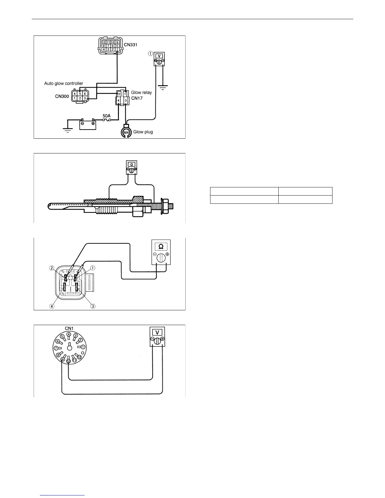
Fig.15
Fig.16
Fig.17
Fig.18
3. Measuring the voltage of the glow plug
(Fig.15)
2
Disconnect the glow plug LE terminal.
2
Key switch: ON
2
Measure the voltage between the LE
terminal and body earth.
* 12 V is indicated and then 0 V is indicated 10
seconds later.
12 V→0 V : The glow lamp is faulty.
Other than 12 V: The glow controller is
faulty.
The glow relay is faulty.
The harness is broken.
4. Inspection of glow plug (Fig.16)
2 Remove the plate between the cylinders.
2 Measure the resistance of the glow plug
alone.
1Ω or less :Normal
More than 1Ω :Faulty
5. Inspection of glow relay (Fig.17)
(1)Measure the glow relay alone.
2 Apply 12 V between (1) and (2) of the glow
relay and check for continuity between (3)
and (4).
Continuity :Normal
No continuity:Faulty
6. Measuring the voltage of the meter coupler
(Fig.18)
2 Disconnect the meter coupler (large).
2 Key switch: ON
2 Measure the voltage between (9) and (10)
of the coupler CN1.
12 V : The meter is faulty.
Other than 12 V : The harness is
broken.Check for
continuity.
Standard value 52 to 80Ω
Measured value About 78Ω

 Loading...