U20-3, U25-3 WSM Machine body (Service section)
II-S-33
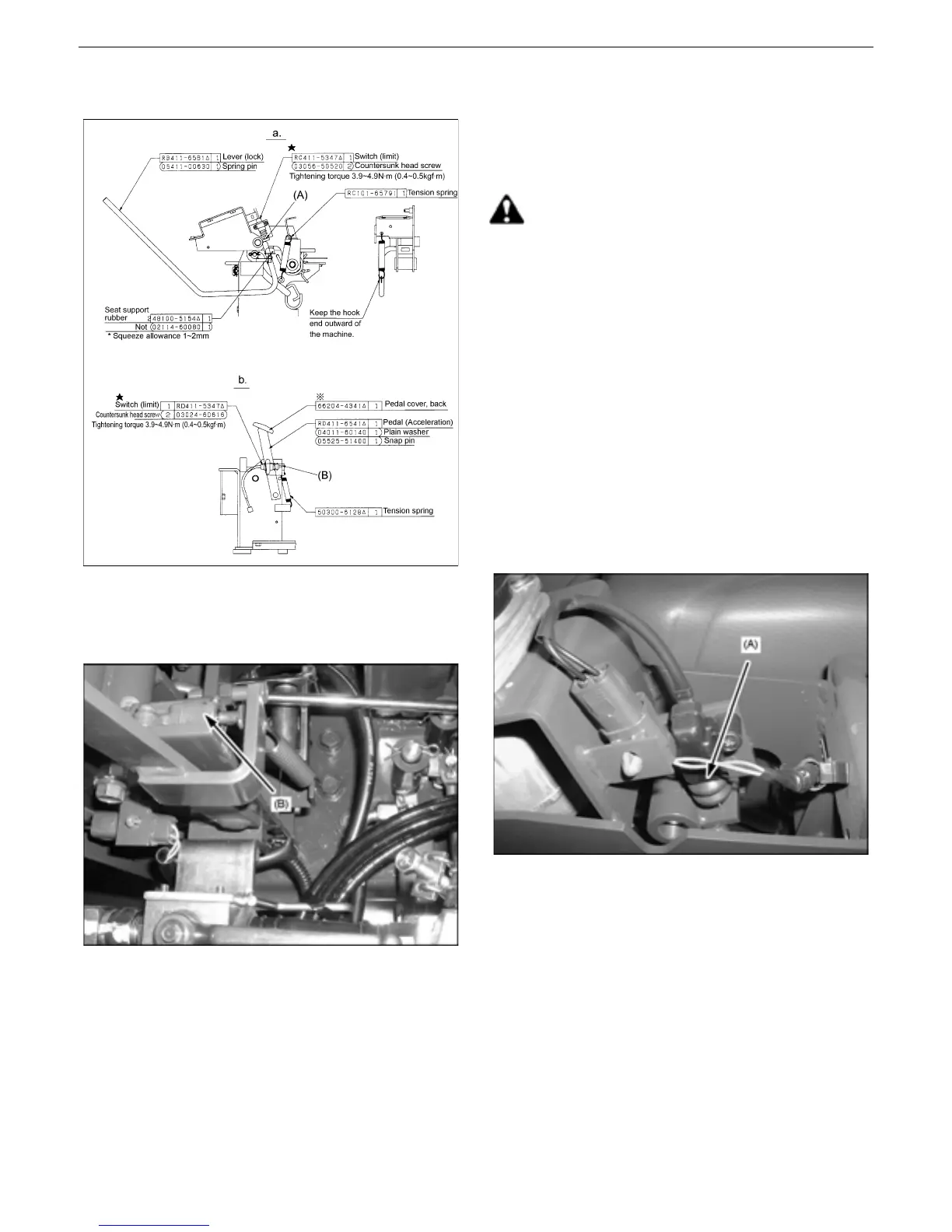
[5] Limit switch
Limit switch setup view
a. Unload lever, left
b. High-speed traveling pedal
High-speed traveling pedal
1) Assembling procedure
1. Tightening torque of limit switch
3.9~4.9N·m (0.4~0.5kgf·m)
Apply screw LOCTITE. (Three-
BondTB1401B)
CAUTION
Allow no gap at the points (A) and (B) when the
limit switch is activated.
2. Apply instantaneous adhesive to the
acceleration pedals rubber cover and
attach it in place.
3. Hook the tension spring to the unload lever
(left).
Make sure the end of the spring hook at the
unload lever faces outward of the machine.
4. Squeeze allowance of seat support rubber
1~2mm
5. Apply grease to the DU bushing bearing.
Limit switch, left

 Loading...