6. CYLINDER HEAD/VALVES
9-2
G-Dink 300i
SERVICE INFORMATION
GENERAL INSTRUCTIONS
• The cylinder head can be serviced with the engine installed in the frame. Coolant in the radiator
and water jacket must be drained first.
• When assembling, apply molybdenum disulfide grease or engine oil to the valve guide movable
parts and valve arm sliding surfaces for initial lubrication.
• The valve rocker arms are lubricated by engine oil through the cylinder head engine oil passages.
Clean and unclog the oil passages before assembling the cylinder head.
• After disassembly, clean the removed parts and dry them with compressed air before inspection.
• After removal, mark and arrange the removed parts in order. When assembling, install them in
the reverse order of removal.
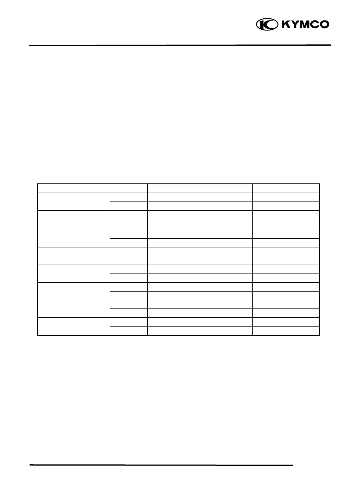
SPECIFICATIONS Unit: mm (in)
Item Standard Service Limit
IN 0.1 mm (0.004 in) ⎯
Valve clearance (cold)
EX 0.1 mm (0.004 in) ⎯
Cylinder head compression pressure 15 kg/cm
2
(213 psi, 1500 kPa) ⎯
Cylinder head warpage ⎯ 0.05 (0.002)
IN 34.2987 (1.371948) 34.14 (1.3656)
Camshaft cam height
EX 34.1721 (1.366884) 34.02 (1.3608)
IN 10 (0.4)~10.015 (0.4006) 10.1 (0.404)
Valve rocker arm I.D.
EX 10 (0.4)~10.015 (0.4006) 10.1 (0.404)
Valve rocker arm shaft IN 9.972 (0.399)~9.987 (0.3995) 9.9 (0.396)
O.D. EX 9.972 (0.399)~9.987 (0.3995) 9.9 (0.396)
IN 4.975 (0.199)~4.99 (0.1996) 4.925 (0.197)
Valve stem O.D.
EX 4.955 (0.1982)~4.97 (0.1988) 4.915 (0.1966)
IN 5 (0.2)~5.012 (0.2005) 5.03 (0.2012)
Valve guide I.D.
EX 5 (0.2)~5.012 (0.2005) 5.03 (0.2012)
Valve stem-to-guide IN 0.01 (0.004)~0.037 (0.0015) 0.08 (0.0032)
clearance EX 0.03 (0.0012)~0.057 (0.0023) 0.1 (0.004)
TORQUE VALUES
Cylinder head cap nut 25 N•m (2.5 kgf•m, 18 lbf•ft) Apply engine oil to threads
Valve clearance adjusting nut 9 N•m (0.9 kgf•m, 6.5 lbf•ft) Apply engine oil to threads
Cylinder head cover bolt 12 N•m (1.2 kgf•m, 8.6 lbf•ft)
SPECIAL TOOLS
Valve spring compressor A120E00040
6-2
 Loading...