17. BATTERY/CHARGING SYSTEM
17-8
MXU 500
Measure the resistance between each Yellow
wire terminals.
Standard: 0.1-0.3 : (20ºC/68ºF)
Check for continuity between each Yellow
wire terminal of the alternator side connector
and ground.
There should be no continuity.
Replace the alternator stator if resistance is
out of specification, or if any wire has
continuity to ground.
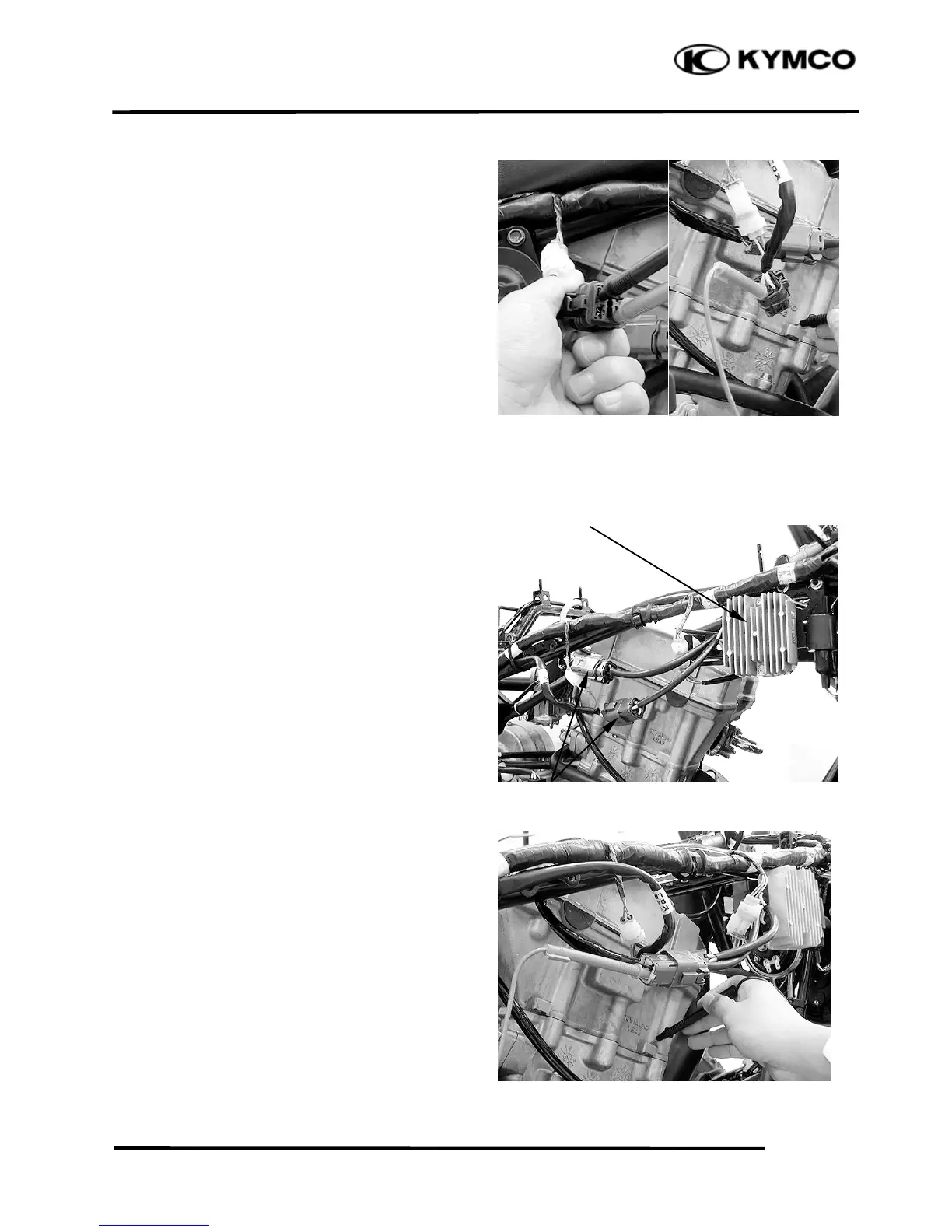
REGULATOR/RECTIFIER
WIRE HARNESS INSPECTION
Disconnect the regulator/rectifier connectors.
Check the connectors for loose contacts of
corroded terminals.
Battery line
Measure the voltage between the Red/White
wire terminal and ground.
There should be battery voltage at all times.
Voltage feedback line
Measure the voltage between the black wire
terminal and ground.
There should be battery voltage with the
ignition switch “ON”, and no voltage with the
ignition switch “OFF”.
Regulator/Rectifie

 Loading...