20. LIGHTS/SWITCHES
20-5
MXU 500
IGNITION SWITCH
INSPECTION
Disconnect the ignition switch connectors.
(Refer to the “FRAME COVER” section in
the chapter 2.)
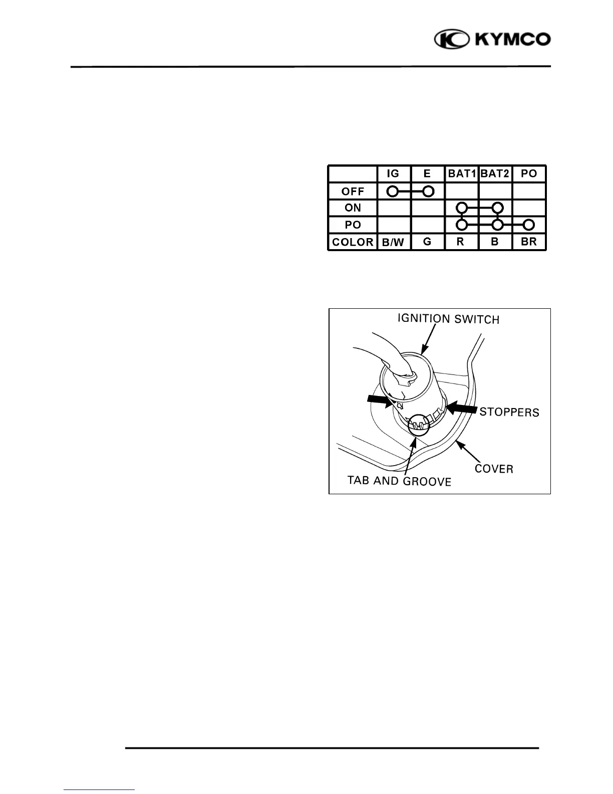
Check for continuity between the switch
side connector terminals in each switch
position.
Continuity should exist between the color
coded wires as right:
REPLACEMENT
Release the switch wire from the wire clips
on the steering shaft holder frame pipe.
Remove the meter cover (refer to the
“FRAME COVER” section in the chapter
2).
Remove the ignition switch from the cover
while pushing in the two stoppers.
Install a new ignition switch by aligning the
locating tab with the groove in the cover.
Install the removed parts in the reverse
order of removal.
HANDLEBAR SWITCH
INSPECTION
Remove front center cover (refer to the
“FRAME COVER” section in the chapter
2).
Disconnect the connectors.
Check for continuity between the switch
side connector terminals in each switch
position.
Continuity should exist between the color
coded wires as next page:

 Loading...