Settings Condition on delivery
Processor card
Note:
Continuous channels must all be fitted with additional cards from
channel 1 onwards
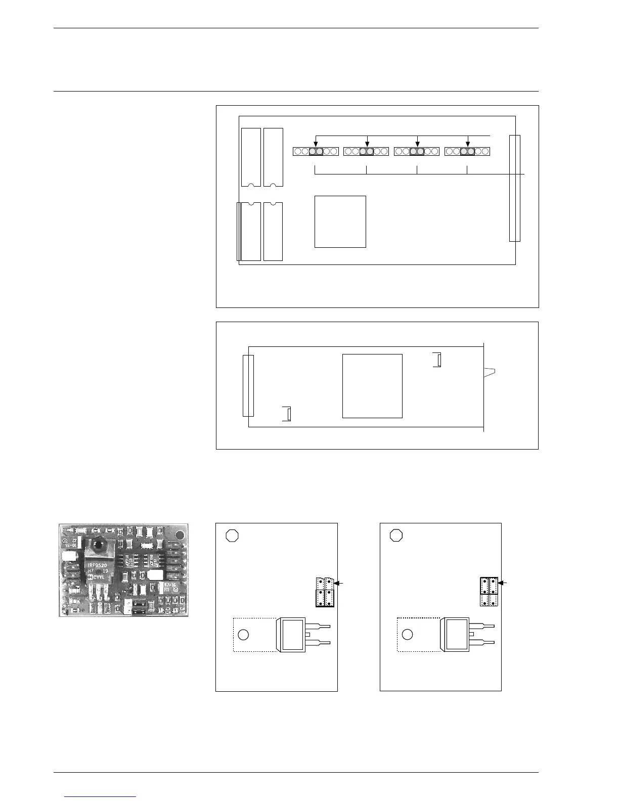
Power supply card
Plug-in p.c. card for The standard control outputs are three-point step
a continuous output (except for a possible 5-channel. This is always continuous).
Each TPS output can be reconfigured to make it continuous by plugging in
an additional card.
The jumpers serve only for hardware switching between current output
and voltage output.
The selection of 0 or 4 … 20 mA is done through the software by means
of parameters.
18
T 902
EEprom for curves
and parameters
Monitoring processor
EEprom for curves
and parameters
Main processor
Program processor
Main processor
Program EPROM
Over-voltage
processor
Sockets for contiuous additional cards
TPS
Configuration
Channel 1
Transformer
Fuse 2
1 AT mA
80 C 537
Channel 2 Channel 3 Channel 4
Bridge
voltage
output
0 … 10V
Bridge
current
output
0/4...20mA
T 902

 Loading...


