FMS Commissioning Correction
________________________________________________________
Set correction input If corrective intervention is desired: Aids
Make sure that correction input is set
Correction signal: terminals 27 and 29 (correction input 1) or
Correction signal: terminals 33 and 34 (correction input 2)
The correction is set via the parameter numbers 429-676, of
which, however, only a fraction are generally released for use
by the person commissioning.
The following settings are possible,
expert level only (level 2):
Current signal:
Correction input 1 0 … 20 or 4 … 20 mA Parameter 431
Correction input 2 0 … 20 or 4 … 20 mA Parameter 432
Correction mode:
Correction mode for correction input 1 Parameter 437
Correction mode for correction input 2 Parameter 441
________________________________________________________
Correction mode and input signal are quoted in the order and are
set at the factory. Any change on site is possible only by
parameter intervention at expert level.
63
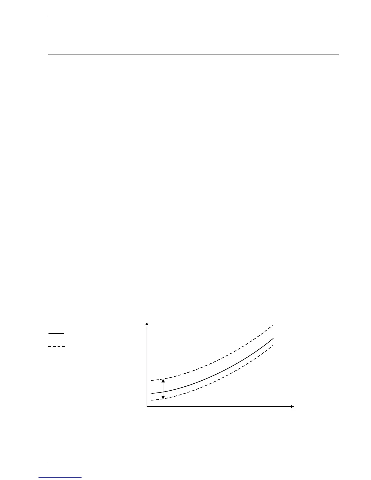
Available correction modes The correction mode specifies how the correction should act.
Manifold settings are possible. Diagrams 1 and 2 show two
typical correction modes for O correction.
2
Type 1: correction acting Type 1 is used if the correction is applied to a linear actuator,
on the target value e.g. a frequency converter shifting the combustion air blower's
rotation speed. The correction is directly added to, or subtracted
from, the target value.
Correction mode: acting on the target value axis
= programmed curve
= correction range
If the correction is applied to a fuel actuator, the effect is
reversed so that 0% corresponds to the smallest target value.
By using the expansion factor held in parameter 433 - Commis-
sioning level - the correction effect can also be weighted across
the burner's output.
0 %
60 %
100 %
Load
Air actuator
Correction range
+ 60 % ...- 40 %
Neutral
value

 Loading...


