FMS Commissioning Programming Curves
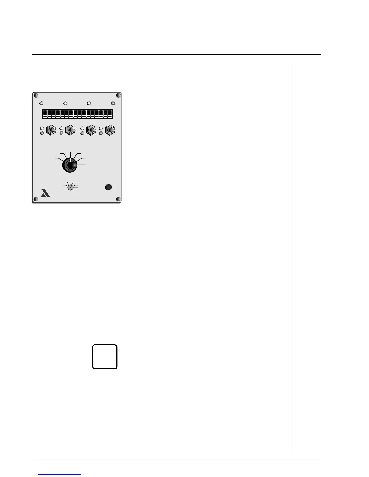
Changing curve point Mode selector switch (2) to "Setting” Aids
Selector switch (1) to "Load rating”
Run to load rating with switch channel 1
the set-points of which are to be altered. Recognisable by the
flashing digits after the load rating, e.g. 687 (8) D2
________________________________________________________
A digit or "Z” must appear after the load rating, otherwise the
VMS does not accept the change and a point may be
accidentally added.
________________________________________________________
Selector switch (1) to "Set-point”
Switch (4) up or down
until system is optimally adjusted at the selected load rating D1,C1,E2
On FMS 5: Selector switch (1) to "Channel 5 display”
- set point and actual value feedback are displayed.
Switch (4) (channel 2) up or down
until channel 5 is optimally adjusted
Selector switch (1) to "Actual value feedback”
Wait until feedback has stopped
Press Acceptance (3)
- Point X (number of the new load rating) appears on the display A16
if necessary
change another curve point
otherwise
Store A5, A10
Check monitoring values
________________________________________________________
The separate ignition point can also be started up and altered
in this way.
________________________________________________________
i
48
LAMTECLAMTEC
xxx
xxx
xxx
xxx
4
3
2
1
SETTING

 Loading...


