Calculation and setting
of control parameters
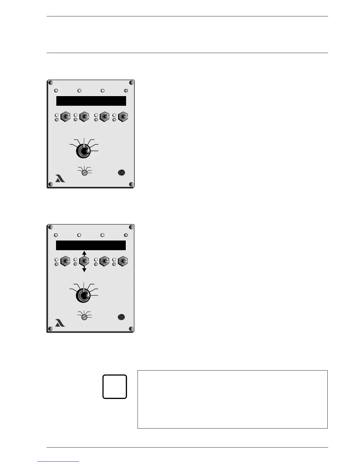
- Manual Run burner on low load.
Set selector switch (2) to O regulation
2
Text message appears
Push channel key 4 (5) downwards
Text message disappears
Set selector switch (1) to target value
Push channel key 2 (4) upwards
The O regulator is activated when this is set.
2
The O target value can now be adjusted using channel key 3 (6) within a
2
range of +3 to -1 vol.% O from the target value entered. The change in the
2
actual O value can be observed at the same time on the display.
2
Channel key 3 (6) upwards Z more O
2
Channel key 3 (6) downwards Z less O
2
The setting of parameters 898/899 and 900 should be such that the next
target/actual value comparison (actuation pulse) takes place only if the O
2
actual value has changed discernibly. A symbol +;-at the centre of the target
value display indicates that a target/actual value comparison is being
performed.
No change or change too small:
Increase P-factor parameter 899.
For details see page 60.
Note: The P-factor (proportionality factor, parameter 899) is specified by
means of the parameter setting. The new correction is obtained
from the two input quantities, deviation and P-factor. The former is
then output to the FMS/VMS.
The procedure is repeated after the lag time's expiry. If the internal
load has changed during this time, the O regulator exits this
2
routine. It must then be reactivated again as described above, via
channel key 2 (4).
Deactivating test mode
Push channel key 2 (4) downwards
FMS Commissioning O regulation
2
Commissioning
Calling up the Turn selector switch (1) to Status
correction range set
Press the Acceptance key (3)
The selected correction range appears on the display.
If both correction inputs act on one channel, the sums are shown.
Press the Acceptance key (3) again, or
turn selector switch back (1) Z return to normal display.
___________________________________________________________________
The correction should be taken into account during later programming.
The correction should be able to act without the FMS reaching the end
of its travel (0 or 999 or end-switch values).
If the correction cannot drive the servo because a channel has reached the
range limit obtained during pre-ventilation, burner output is increased or
decreased until the correction can be effected. This function can be
switched off via the parameter 0 - Release level 2. Content 0 Z off!
___________________________________________________________________
_
xxx
xxx
xxx
3
C
2
LAMTECLAMTEC
xxx
1
59
K1 - 30 70
i
xxx
xxx
xxx
4
6
5
1
LAMTECLAMTEC
xxx
2
O2 I 2.3 T 2.7
T-On
T-Off

 Loading...


