99
5 Functional Description with Process Diagrams
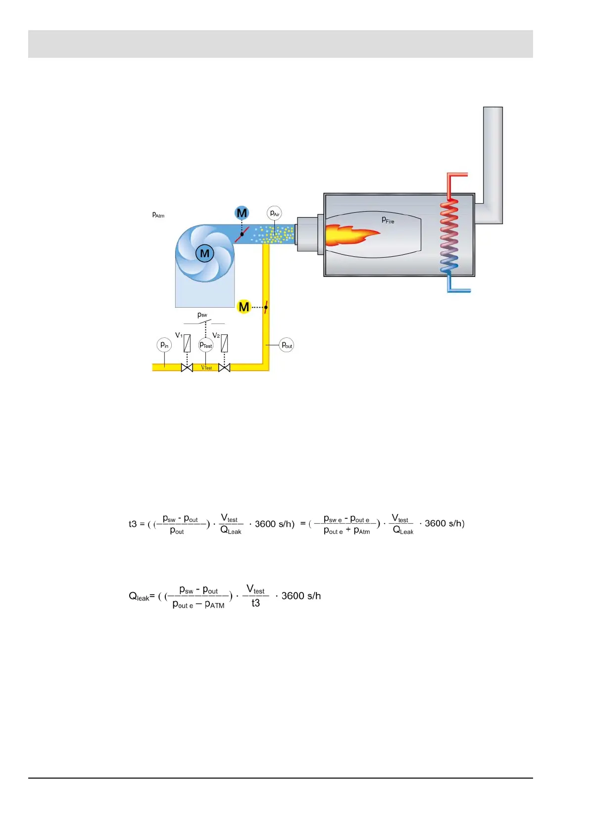
Calculation
Fig. 5-17 Schematic
The test volume V
test
must be calculated from the pipe diameter and the valve volumes. The
valve volumes are specified by the valve manufacturer. If a double valve is utilised as valve 1
and valve 2, the test volume will be specified by the valve manufacturer.
The leakage volume V
Leak
is calculated with the help of Boyle's law.
p
1
V
1
= p
2
V
2
p = absolute pressure
V = gas volume
The following applies for the valve 1 test:
If t3 is negative, at least 1 s must be configured.
If the t3 calculation for valve 2 yields a value larger than t3 for valve 1, the value must be con-
figured that was calculated for valve 2.
Q
leak
Leakage rate in l/h
p
sw
Absolute pressure at pressure monitor switching point (configured excess pres-
sure + atmospheric pressure)
p
sw e
Excess pressure configured at pressure monitor switching point
p
out e
Excess pressure at gas valve V2 output at the time of block and bleed
p
Atm
Atmospheric pressure (average of 101.3 kPa at sea level)
V
test
Test volume between the valves
t3 Configured test time CMS
 Loading...

