100
5 Functional Description with Process Diagrams
NOTICE
p
switch
must always be larger than p
out
.
If not, a leak will be detected at V1 even though V1 is leak-tight.
The following applies for the valve 2 test:
If t3 is negative, at least 1s s must be configured.
If the t3 calculation for valve 1 yields a value larger than t3 for valve 2, the value must be con-
figured that was calculated for valve 1.
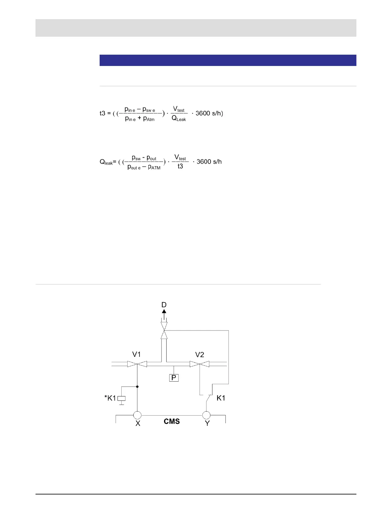
5.2.6.7 Suggested Circuit For Venting
Q
leak
Leakage rate in l/h
p
sw
Absolute pressure at pressure monitor switching point (configured excess pres-
sure + atmospheric pressure)
p
sw e
Excess pressure configured at pressure monitor switching point
p
in
Absolute inlet pressure at gas valve V1
p
in e
Excess inlet pressure at gas valve V1
p
Atm
Atmospheric pressure (average of 101.3 kPa at sea level)
V
test
Test volume between the valves
t3 Configured test time CMS
Fig. 5-18 Block and bleed by the roof (recommendation)
D Block and bleed by the roof
V1 Gas-side valve
V2 Burner-side valve
P Gas min.
X Terminal
Y Terminal
 Loading...

