49
4 CMS Components
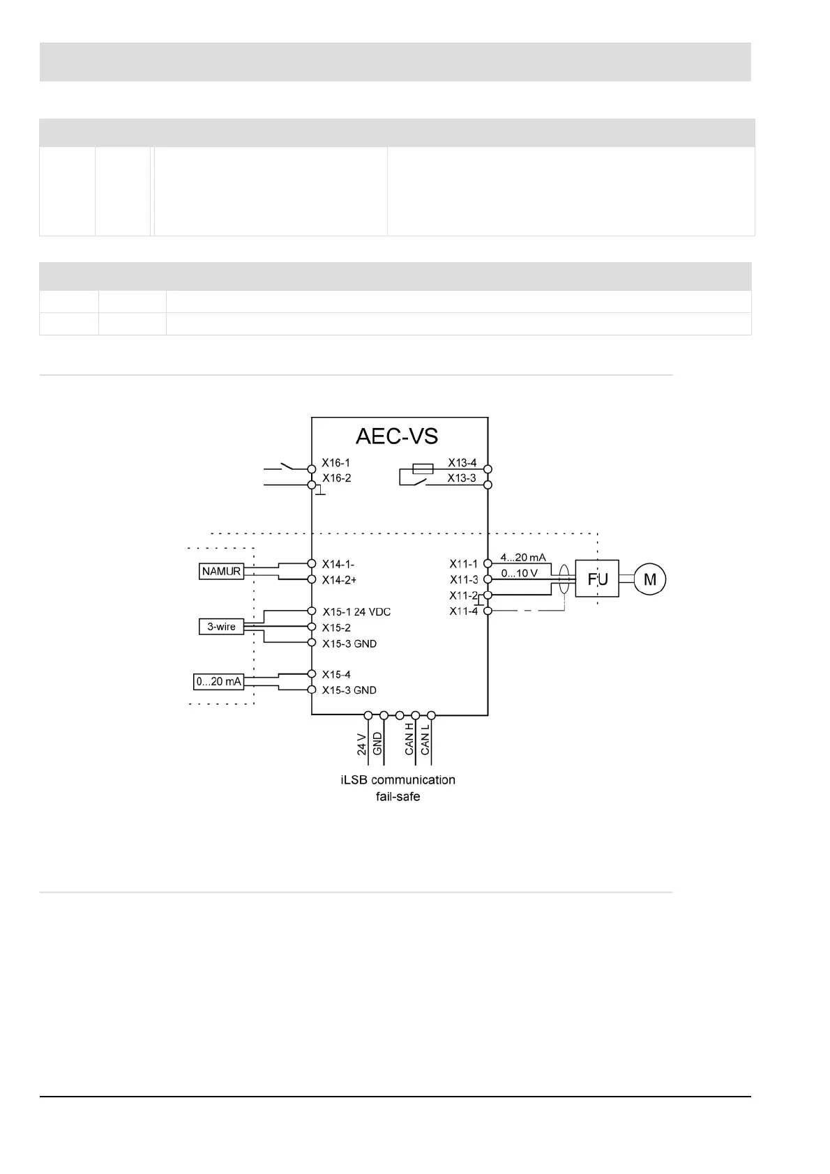
4.3.6 Connection Diagram
Fig. 4-15 AEC-VS connection diagram
* 4 … 20 mA or 0 … 10 V
4.3.7 Interfaces
Failsafe communication via iLSB.
S2 Yel-
low
– Flashing at 2 Hz:
ICOM initialising
– Permanent light:
ICOM successfully
initialised
– Flashing at 2 Hz:
PEC identification activated.
* Passive mode = PEC not taught-in
Burner firing-rate In operation
LED Colour Description
Nam Yellow Each pulse at the Namur input switches the LED. The LED flashes at half pulse frequency.
3-Wire Yellow Each pulse at the 3-wire input switches the LED. The LED flashes at half pulse frequency.
 Loading...

