90
5 Functional Description with Process Diagrams
NOTICE
This function is active only from software version 2.0.
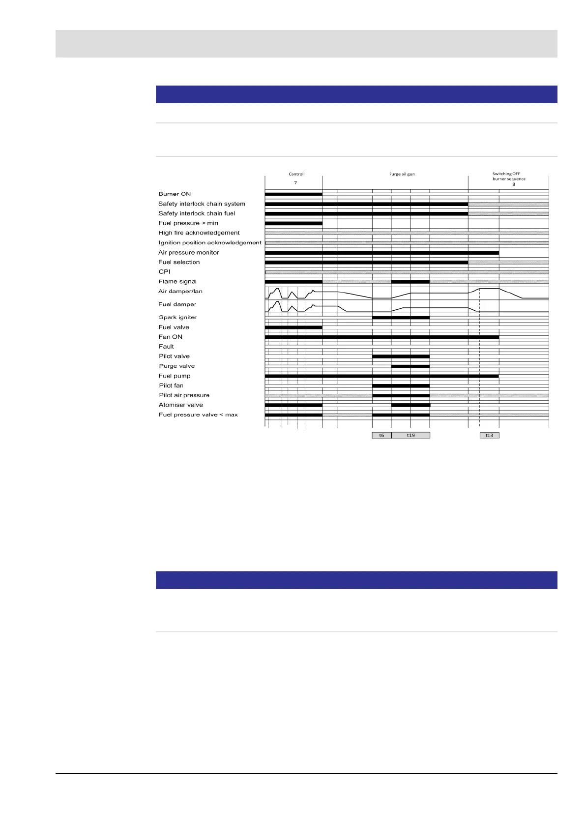
Process Diagram 'Purging after Operation'
Fig. 5-12 Process sequence chart for purging oil gun
t5 is the waiting time until the actuators have reached the purging position. The purging valve
is then opened.
t5 + t3 produce the purging duration (total). During the entire process, the safety interlock
chain oil must be secured.
NOTICE
If the purging valve is activated by P 812 = 1 and after closing the oil valve, without having
waited for t2, t5 first and not having reached the required position, the flame will not be mon-
itored during the time t2.
7 Control t6 Transformer pre-activation time P309 0.0 s - 40.0 s
8 Burner OFF t13 Post-ventilation time P 319 0.0 s - 999 s
t19 Duration of purging P 810 0.0 s - 999.9 s
 Loading...

