Electrical installation
Wiring
EL 1xx ECO (PLC)
6
30
LDCDS−EL100 EN 8.0
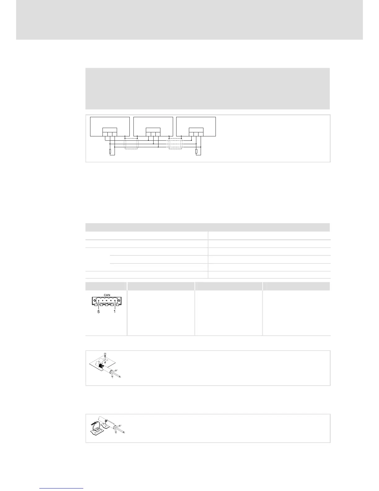
CAN interface
Note!
ƒ Only connect terminals of the same signal type.
ƒ For further information with regard to the CAN bus system please refer to
the CAN Communication Manual.
CG
CAN
LO HI CG
CAN
LO HI CG
CAN
LO HI
RR
A
n
A
2
A
1
EL100−009
A1 Node 1
A2 Node 2
An Node n
CG CAN−GND
LO CAN−LOW
HI CAN−HIGH
R 120 W−bus terminating resistor
We recommend the use of CAN cables in accordance with ISO 11898−2:
CAN cable in accordance with ISO 11898−2
Cable type Paired with shielding
Impedance 120 W (95 ... 140 W)
Cable resistance/cross−section
Cable length £ 300 m £ 70 mW/m / 0.25 0.34 mm
2
(AWG22)
Cable length 301 1000 m £ 40 mW/m / 0.5 mm
2
(AWG20)
Signal propagation delay £ 5 ns/m
Description Connection type Cable type
CAN bus connection
Pin 1: CAN−GND (CG)
Pin 2: CAN−LOW (LO)
Pin 3: CAN−SHIELD
Pin 4: CAN−HIGH (HI)
Pin 5: Not assigned
5−pole Phoenix Combicon
socket
CAN cable acc. to ISO 11898−2
with Phoenix Combicon plug,
MSTB 2.5 / 5−STF−5.08
EL100−011
CAN cable shield connection via cable clamp on the back of the device:
EL100−033
Cable fixing and strain relief
Fix the cable bundles on the back of the EL 103 using cable ties.
EL100−034
 Loading...