Operation
Communicating via the CAN gateway function
Establishing communication using the L−force Engineer
8
75
LDCDS−EL100 EN 8.0
8.5.4 Establishing communication using the L−force Engineer
The used bus system must be selected for the communication via the EL100
communication module. System bus−specific settings can be made on the EL100 module
in the "CAN Gateway" applet. The communication module can only be selected via the
system bus configurator.
Commissioning is illustrated by the following example. The parameter data of an 8400
frequency inverter are to be displayed using the Engineer.
How to proceed:
1. Start the L−force Engineer program and create a new program.
Information on how to proceed is provided in the L−force Engineer documentation.
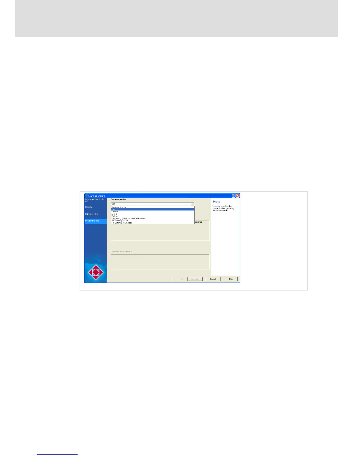
2. Start the search for connected devices.
3. Define the project properties and click Next.
4. Define the storage location of the project and click Next.
5. To be able to access the 8400 frequency inverter via the EL100 communication
module, select the "CAN" bus connection.
EL100−044
 Loading...