DC−bus operation
Basic dimensioning
General information
7
l
118
EDS700ACBA EN 5.1
7.5 Basic dimensioning
7.5.1 General information
The Drive Solution Designer (DSD) PC software helps you to dimension your drive network.
For expert advice, you may also contact your Lenze sales representative when
dimensioning your application.
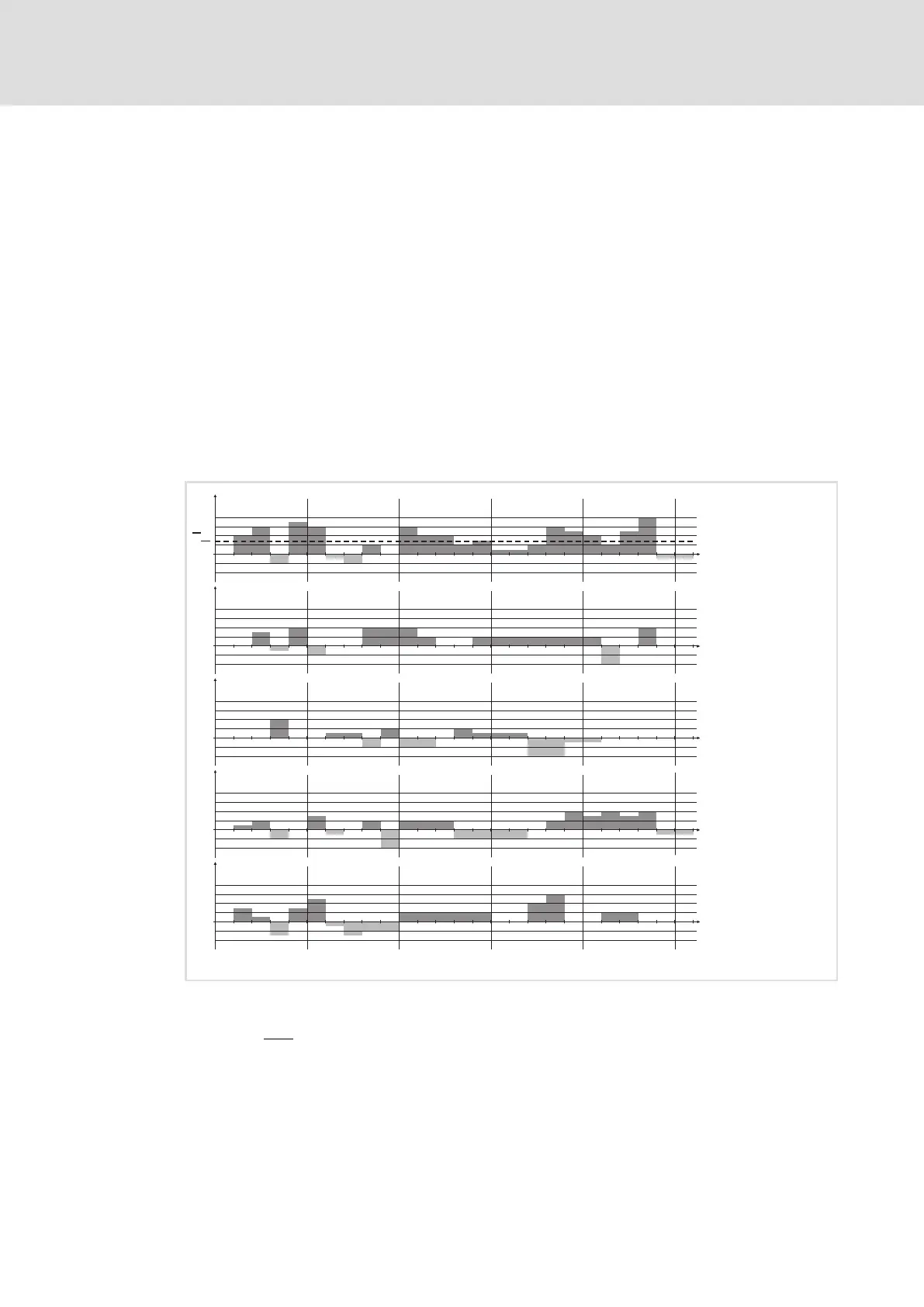
Time/performance diagram
For determining the performance of your drive network, create a time/performance
diagram for all axes for a complete machine cycle. The power requirements of the drive
network are calculated by adding the individual performances occurring at the same time.
Positive results show the AC requirements for the dimensioning of the power supply units.
Negative results show the brake power to be dissipated via brake choppers at the brake
resistor.
0
P
3
0
P
2
0
P
1
12
13
111 2
3
4
5
678910
t
0
P
res
t
0
P
4
13
111 2
3
4
5
678910
12
P
res
T/P−diag001
Fig. 7−1 Example time/performance diagram
P
1
... P
4
Individual performances of axes 1 ... 4
P
total
Addition of the individual performances
P
total
Average of the individual performances
Use the time/performance diagram to optimise the DC−bus performance of all axes for a
complete machine cycle.
 Loading...


